Now this is a real fun part, which I love and am never tired of explaining :)
The routing world awaits. But before we plunge into its depths, it is imperative that we become fluent with conversions between decimal and binary numeral systems. Why? Because all electronic devices such as our beloved computers and routers use binary numbers. On the other hand, we humans tend to use decimal notations almost all the time.
Believe it or not but the binary numeral system is easier to understand than the decimal one. But our problem is that we have been using the decimal notation for so long that looking at anything different feels very awkward.
It is good to know that all numeral systems (binary, octal, decimal, hexadecimal, the-one-you-may-want-to-create) are based on the same foundations. There are two major components of a numeral system: the base and the exponent.

I almost hear your thought: 'Eh... what?' Fear not. It's easy to understand if you remember the math at the elementary level.
The base in the above formula is determined based on how many digits (or characters) we use to denote the number. Consider the decimal system. We have exactly 10 digits to express the volume:0,1,2,3,4,5,6,7,8,9. So, the in decimal numeral system the base = 10 (ten digits available). What happens when we have more of something than 9?
It is simple we engage a new column of numbers on the left and zero the number on the right: 10. This way we get ten. The first column denotes the number of 10s and the next column, denotes the units. As soon as we run out of numbers in the unit columns, we increase the number in the columns of tens. For instance: 17, 18, 19... 20.
What happens when we run out of the number of the column of tens? We add one more column on the left, which is the columns of 100s and zero all other columns on the right. For instance: 97, 98,99... 100.
We know that in the four column number: 1048 the first column (1) on the left denotes thousands, the next to the right (0) denotes hundreds, the one next to it (4) denotes tens, and the last one (8) describes units. The column in each and every numeral system has the weight.
Check the picture below to see this in more detail.

Using the formula you calculate the numbers in decimal as shown in the next picture (pic. 3). Each number in the column must be multiplied by the corresponding weight of the column. These in turn, must be added together to give you the number. Pic. 3 shows that in more detail. Make sure that you understand it before you proceed with your reading.
In exact same way we create others such as the binary numeral system. Here, our base is going to use only two digits: 1 or 0 called bits. Thus, our base = 2 (only two digits available). Since, we most often cluster 8 bits together to form a byte, our colums and weights are going to look as in the picture below (pic. 4).

NOTICE!
Cisco expects their engineers to be able to do the binary-to-decimal and decimal-to-binary conversions WITHOUT using a calculator (using a paper and pen only).
Binary-to-Decimal Conversion
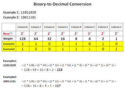
In order to convert the binary number to its decimal equivalent, you must follow the exact same rules explained for decimal system. You multiply the number in the column by its weight in every columns. The products of these multiplications must be added together.Take a look at the example in the pic. 5.
In order to practice those try to quickly convert the following binary to decimal (DO NOT USE A CALCULATOR):
Ex1: 11011010 (calculated above)
Ex2: 10011101 (calculated above)
Ex3: 11001011
Ex4: 00100101
Ex5: 01010101
Ex6: 11111010
Ex7: 01101101.
It should not take you more than a few seconds per example. Check your results using a calculator.
When it comes to opposite conversion it is a bit more difficult, but still at the elementary math level.
Decimal-to-Binary Conversion
The best way to learn how to do the conversion is actually do it and analyse every step of the way.
Example1: the decimal value of 172, to be converted into the binary.
The following table is going to come in handy.

Step 1
Find the closest weight value in the binary table that does NOT exceed the value you convert.
In the example1, the closest weight is: 128. The weight of the next column (here, non-existent column 9) would exceed the value of 172, since the weight of it is 256.
Step 2
In our handy table, write in ‘1’ in the column you have chosen.

Step 3
From the initial decimal number take away the weight you have used (the ‘1’ you put in the table takes away the weight from the number you are converting).
In the example1, the decimal number we have is: 172 and the weight we just used by putting a ‘1’ in our table is: 128. So, our calculation looks like the one below:
Step 4
Check if the number you have left (in our example the value left is: 44) is larger or smaller than the weight of the next column on the right-hand side in our table.
a) If the number you have left is larger than the weight in the next column to the right, put in ‘1’ in the next column and subtract its weight from the number you have left.
b) If the number you have left is smaller than the weight in the next column to the right, put in ‘0’ in the next column and perform the same check against the next column (step 4a). You have to do it until the check in step 4a is true.
In the example1, the value we have left is: 44. We check it against the weight in the next column on the right. The number (44) is smaller than the weight in the next column to the right (64). Since 44 < 64, we follow the instructions in the step 4b.

The next check against step 4a is true! Since 44 > 32, we put in a ‘1’ in the next column and take away the weight (32) from the number we have left (44).

We go back to the step 4.
The number we are left with (12) is smaller than the weight of the next column to the right (16). Since12 < 16, we proceed to the step 4b.

The next check against step 4a is true! Because 12 > 8 we put in a ‘1’ in the next available column on the right and take away its weight (8) from the number we are left with now (12).


Believe it or not but the binary numeral system is easier to understand than the decimal one. But our problem is that we have been using the decimal notation for so long that looking at anything different feels very awkward.
It is good to know that all numeral systems (binary, octal, decimal, hexadecimal, the-one-you-may-want-to-create) are based on the same foundations. There are two major components of a numeral system: the base and the exponent.
Pic. 1 - Numeral System Components - The Formula.

I almost hear your thought: 'Eh... what?' Fear not. It's easy to understand if you remember the math at the elementary level.
The base in the above formula is determined based on how many digits (or characters) we use to denote the number. Consider the decimal system. We have exactly 10 digits to express the volume:0,1,2,3,4,5,6,7,8,9. So, the in decimal numeral system the base = 10 (ten digits available). What happens when we have more of something than 9?
It is simple we engage a new column of numbers on the left and zero the number on the right: 10. This way we get ten. The first column denotes the number of 10s and the next column, denotes the units. As soon as we run out of numbers in the unit columns, we increase the number in the columns of tens. For instance: 17, 18, 19... 20.
What happens when we run out of the number of the column of tens? We add one more column on the left, which is the columns of 100s and zero all other columns on the right. For instance: 97, 98,99... 100.
We know that in the four column number: 1048 the first column (1) on the left denotes thousands, the next to the right (0) denotes hundreds, the one next to it (4) denotes tens, and the last one (8) describes units. The column in each and every numeral system has the weight.
Check the picture below to see this in more detail.
Pic. 2 - Decimal Numbers - Formula.

Pic. 3 - Example of Decimal Numbers According to the Formula.


Pic. 4 - Binary Numbers - Formula.

NOTICE!
Cisco expects their engineers to be able to do the binary-to-decimal and decimal-to-binary conversions WITHOUT using a calculator (using a paper and pen only).
Binary-to-Decimal Conversion
In order to convert the binary number to its decimal equivalent, you must follow the exact same rules explained for decimal system. You multiply the number in the column by its weight in every columns. The products of these multiplications must be added together.Take a look at the example in the pic. 5.
Pic. 5 - Examples of Binary-to-Decimal Conversion.

Ex1: 11011010 (calculated above)
Ex2: 10011101 (calculated above)
Ex3: 11001011
Ex4: 00100101
Ex5: 01010101
Ex6: 11111010
Ex7: 01101101.
It should not take you more than a few seconds per example. Check your results using a calculator.
When it comes to opposite conversion it is a bit more difficult, but still at the elementary math level.
Decimal-to-Binary Conversion
The best way to learn how to do the conversion is actually do it and analyse every step of the way.
Example1: the decimal value of 172, to be converted into the binary.
The following table is going to come in handy.
Pic. 6 - Decimal-to-Binary Conversion.

Step 1
Find the closest weight value in the binary table that does NOT exceed the value you convert.
In the example1, the closest weight is: 128. The weight of the next column (here, non-existent column 9) would exceed the value of 172, since the weight of it is 256.
Step 2
In our handy table, write in ‘1’ in the column you have chosen.
Pic. 7 - Decimal-to-Binary Conversion.

Step 3
From the initial decimal number take away the weight you have used (the ‘1’ you put in the table takes away the weight from the number you are converting).
In the example1, the decimal number we have is: 172 and the weight we just used by putting a ‘1’ in our table is: 128. So, our calculation looks like the one below:
172 – 128 = 44
Step 4
Check if the number you have left (in our example the value left is: 44) is larger or smaller than the weight of the next column on the right-hand side in our table.
a) If the number you have left is larger than the weight in the next column to the right, put in ‘1’ in the next column and subtract its weight from the number you have left.
b) If the number you have left is smaller than the weight in the next column to the right, put in ‘0’ in the next column and perform the same check against the next column (step 4a). You have to do it until the check in step 4a is true.
In the example1, the value we have left is: 44. We check it against the weight in the next column on the right. The number (44) is smaller than the weight in the next column to the right (64). Since 44 < 64, we follow the instructions in the step 4b.
Pic. 8 - Decimal-to-Binary Conversion.

Pic. 9 - Decimal-to-Binary Conversion.

44 – 32 = 12
We go back to the step 4.
The number we are left with (12) is smaller than the weight of the next column to the right (16). Since12 < 16, we proceed to the step 4b.
Pic. 10 - Decimal-to-Binary Conversion.

The next check against step 4a is true! Because 12 > 8 we put in a ‘1’ in the next available column on the right and take away its weight (8) from the number we are left with now (12).
Pic. 11 - Decimal-to-Binary Conversion.

12 - 8 = 4
The difference is: 4. I hope you already know what is going to happen. Step 4a is true, so we put in a ‘1’ in the column and take away the weight from the number.
Pic. 12 - Decimal-to-Binary Conversion.

4 - 4 = 0
The difference now reaches 0, so we fill in the remaining columns with 0.
Pic. 13 - Decimal-to-Binary Conversion.

In order to practice those try to quickly convert the following binary to decimal (DO NOT USE A CALCULATOR):
Ex1: 172 (calculated above)
Ex2: 67
Ex3: 124
Ex4: 168
Ex5: 215
Ex6: 237
It should not take you more than a few seconds per example. Check your results using a calculator.
Ex2: 67
Ex3: 124
Ex4: 168
Ex5: 215
Ex6: 237
It should not take you more than a few seconds per example. Check your results using a calculator.
Understanding and fluency with the conversion is the pre-requisite to calculating IP subnets, maximizing the addresses per subnets etc.
In my next post, we will take a look at IP address and play with subnet calculations.


