Showing posts with label number. Show all posts

Mar 13, 2013

Lesson 55 - Introduction to IPv6 - Addresses


Network Address Translation I have rambled about in the last four posts, is designed to deal with a rapid IPv4 address depletion. The scope of 32 bits, allows to allocate 4 294 967 296 unique numbers. Even though, it seemed a lot in late 80s, the exponential growth of the Internet in 90s showed us that 4.3 billion addresses are not enough to uniquely identify our devices these days. The solution to the problem, at least for now, is to use IP version 6.

But what happened to IPv5?
I have found the answer to this question at:
http://compnetworking.about.com/b/2008/11/05/what-happened-to-ipv5.htm

IPv6 Header
IPv6 Header has been simplified in order to improve the efficiency on the routers. Fewer header fields to process, allow faster transmissions. Take a look at the comparison between IPv4 and IPv6 headers:
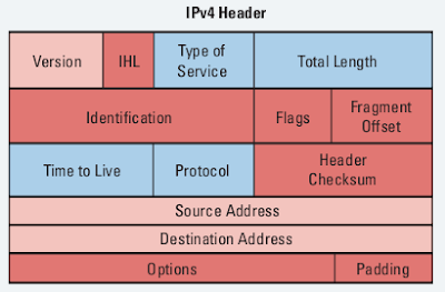
Pic. 1 - IPv4 Header.

Pic. 2 - IPv6 Header.
Pic. 3 - IPv4 and IPv6 Header Field Comparison.
Source:
http://www.cisco.com/en/US/tech/tk872/tech_white_papers_list.html

(IPv6 Headers at Glance.pdf)

IPv6 header does not use checksum, the TTL field has been replaced with Hop Limit name, and packets will no longer be fragmented (Path MTU Discover is going to be performed or the minimum MTU must be used: 1280 bytes).

IPv6 uses 128-bit addresses and offers us quite a number of unique identifiers:

3.4 x 10 ^ 38

So the number of addresses available is this:

340,282,366,920,938,463,463,374,607,431,768,211,456

Chances are that we will not run out of these till the end of this century.

In IPv6 designers gave up on broadcast transmissions. They have been replaced with multicast and unicast.

IPv6 Address Notation
Decimal notation has been replaced with hexadecimal using 16 characters (0,1,2,3,4,5,6,7,8,9,a,b,c,d,e,f). A=10, B=11, C=12 etc. You can use both upper and lower cases to address your device since the numbers are case insensitive.

IPv6 address consists of eight groups of four characters (2-byte values) delimited with the colon (:). Take a look at this address:

2001:0db8:65a3:0000:0000:5d2e:0370:7134

Addresses still use the hierarchy like we in IPv4. They are divided into two parts. The green one (64 bits) denotes the network portion, and the blue one is a interface identifier. Since it would be tedious to type in all these numbers, we can use few shortcuts. 

  • Leading zeros can be omitted
  • Groups of four zeros can be abbreviated to a zero
  • Multiple contiguous groups (2-byte groups) can be abbreviated to double colon (::) but only once.
Look at these examples below.

Leading zeros omitted: 
2001:0db8:65a3:0000:0000:5d2e:0370:7134 can be abbreviated to:
2001:db8:65a3:0000:0000:5d2e:370:7134

Groups of four zeros can be abbreviated to a zero:
2001:0db8:65a3:0000:0000:5d2e:0370:7134 can be abbreviated to:
2001:0db8:65a3:0:0:5d2e:0370:7134 can be abbreviated to:

Multiple contiguous groups (2-byte groups) can be abbreviated to double colon (::) but only once
2001:0db8:65a3:0000:0000:5d2e:0370:7134 can be abbreviated to:
2001:0db8:65a3::5d2e:0370:7134

Following all these shortcuts:
2001:0db8:65a3:0000:0000:5d2e:0370:7134 will be represented

2001:db8:65a3::5d2e:370:7134

Types of IPv6 addresses
There are few types of addresses w need to know about. These are:

  1. Global Addresses - Unique, global addresses used on the Internet. They use the following prefix 2000::/3.
  2. Link Local Addresses - Used to communicate with hosts on the same physical or logical network. These addresses start with FE80::/10
  3. Site Local Address - The equivalent of RFC1918 (private addresses) but they are being deprecated. They start with FEC0::/10 prefix.
  4. Multicast Address - Multicast replaces broadcast (along with unicast). The addresses use the following prefix: FF00::/8.
In my next post, I will show you simple configuration of these addresses on the command line interface.

Lesson 47 - Packet Filtering with Standard ACL


NOTICE!
Access Control Lists can inspect the traffic based on different protocols and criteria. In this post I’m going to focus in on IP-based ACLs. Other types such as MAC-based ACLs, dynamic or reflective ACLs are beyond the scope of this tutorial.

Have you noticed how your hand luggage is being scanned at the airport? ACL is similar to such scanner only used on the router. It can look at the content of the packet traversing it and check the content of the packet up to the layer 4 (extended ACL). You, as an administrator, get to decide what the action is going to be if the packet matches your criteria. A few applications of ACLs are as follows:

  • ACLs can filter the packets that traverse the router in order to drop the unwanted traffic.
  • ACLs can deny SSH or Telnet traffic to vty lines (router/switch remote management).
  • ACLs are used as to match an interesting traffic to trigger VPN tunnel establishment and encrypt data.
  • ACLs are commonly used in Quality of Service to prioritize certain applications or traffic flows over others or provide different treatment to a certain stream of packets.
  • ACLs are used to filter inbound or outbound dynamic protocol advertisements.
  • Etc.
To summarize it: you cannot call yourself a network specialist without being able to use ACLs. In this tutorial, we focus in on IP based ACLs.

IP  Based ACLs
You can use two major IP-based ACLs (look at the guidelines above):

  1. Standard ACLs (numbers: 1 through 99)
  2. Extended ACLs (numbers: 100 through 199)
  3. Named ACL (standard or extended). Named ACLs offer more flexibility in terms of modifying ACLs 'on the fly'
The major differences between them are the amount and type of criteria we can use to inspect the packets as well as the syntax used to create the statement.

In this post I present IP standard ACL only used as a filtering mechanism (permit or deny the traffic through the router), but get familiar with the general guidelines first as they apply to all types and applications of ACLs.

ACL Guidelines
Here are some important guidelines regarding ACLs:

  • ACLs use the top-down processing. This means that statements are being processed from the one listed on the top of the list first. If the statement is a successful match (permit or deny), the remaining entries listed below this matching statement are NOT inspected anymore.
  • Cisco IOS allows to apply only one ACL per interface, protocol and direction. This means that you can apply ACL1 on two different interfaces, or ACL1 and ACL2 on the same interface but in two different directions (in and out).
  • The ACL number will determine whether it is IP standard ACL (numbers 1-99) or IP extended ACL (numbers 100-199).
  • Standard ACL can only inspect the source IP of the packet.
  • Extended ACL will inspect both source and destination IP. In addition to these it can match on layer 4 protocols (TCP, UDP, OSPF, EIGRP etc.) and even the layer 4 port numbers (either source or destination or both).
  • The standard ACLs should be placed close to the destinationextended ACLs should be placed close to the source of the transmission.
  • There is an IMPLICIT DENY ALL at the end of all the statements that you create. This means, that if your statements have been created to deny traffic, there must be at least a single permit statements. Otherwise all traffic crossing the interface where ACL has been configured will be denied (filtered out).
The process of configuring ACLs consist of two steps:
  1. Configuring the ACL statements in the global configuration mode.
  2. Applying the ACLs on the interfaces to inbound or outbound traffic.
Standard Access Lists
Standard ACL offers you only a single criterion to single packets out from the flows a router handles. It is a source IP address. Based on this criterion, a router determines if the packet should be forwarded or dropped. This type of ACL does not check if IP carries TCP, UDP, OSPF, EIGRP etc. Based on the source IP address the “whole” IP packet (irrespective of the layer 4-5 content) will be forwarded or dropped.

This time, I'm going to show you the syntax taken directly from the Cisco web site. The point is, that sooner or later you have to learn how to use the official Cisco Documentation. You must learn how to be self-reliant at your work because in many cases you will not have anyone around to take you by the hand and solve an issue.

The ultimate source of all Cisco related configurations can be found at (here IOS 12.4 version):

http://www.cisco.com/en/US/products/ps6350/tsd_products_support_series_home.html 

Pic. 1 - IP Standard ACL Syntax.
Pic. 1 shows you the standard ACL syntax you type in the 'config' mode (global configuration mode. 
  • access-list - the ACL keyword that is followed by a number of argument
  • access-list-number - IP standard ACLs use the numbers in the range 1-99
  • permit|deny - what is in braces '{}' are possible options; here permit or deny
  • host|source - again in braces '{}' are possible options; here either a host address or other source such as network or subnet.
  • source-wildcard|any - this is the inversed network mask ('1' becomes '0' and vice versa).
Bold font is the keyword that you must use.
Italic font is the arguement that follows the keyword.
| - a pipe is the logical 'or' statement giving you multiple choices.
{} - in braces the possible options are listed.

The next step in configuring an ACL (standard or Extended) is to apply it on the interface in either inbound or outbound direction.

Pic. 2 - Applying ACL on the Interface.
interface - the keyword to enter the interface context (must be in the 'config mode')
<interface> - type/number of the interface (e.g. interface Fa0/0)
ip access-group - the keyword that applies an ACL on the interface
number - the number of access-list configured in the 'config' mode (standard ACL use range 1-99)

in|out - the direction inbound or outbound (how packets are going to be processed)

INBOUND ACLs 
This type of ACL analyzes the packets coming towards the router (the interface where packet was received on). Based on the criteria defined in the ACL, the packet will further be processed (layer 3 lookup performed trying to find the outbound interface), or dropped.

OUTBOUND ACLs 
If you apply the ACL as 'out' the incoming interface does NOT compare the packet content with the ACL statements. It performs a layer 3 lookup immediately. Once the outbound interface is found, and the ACL is applied there as 'out' it analyzes the ACL statement one by one (top-down). Once the match is found (permit or deny) the packet is or is not sent out that interface.

Remember, that IP standard ACLs check the source IP only!


In the next post, I show you a few examples of IP standard ACL with a detailed analysis how they work. This and the next post should get you going with IP standard ACLs.

Lesson 44 - EIGRP Fundamentals Part 2 - Implementation


In the previous post (lesson 43) I have laid the foundations related to EIGRP terminology. Without understanding those keywords and their meaning it is hard to implement and analyze the behavior of this routing protocol.

The basic implementation steps, like in case of other routing protocols we have learned so far, requires two major steps:

  1. Enable EIGRP process in the 'config' mode.
  2. Instruct EIGRP which interfaces should participate in the EIGRP domain.
The second step is accomplished with the 'network' statement in the EIGRP routing context. This statement instructs EIGRP routing process which interfaces EIGRP will run on. The consequences of enabling EIGRP on the interface are similar to what we saw in OSPF configuration:
  • EIGRP-enabled interface begins to send EIGRP 'hello' packets in order to discover the neighbors. The address used to advertise these 'hello' packets is well-known, reserved multicast address: 224.0.0.10.
  • EIGRP-enabled interface allow the EIGRP process to read the address and network mask configured on this interface and advertise this network or subnet out other EIGRP-enabled interfaces where the neighbor(s) has/have been discovered and the relationship has been formed with them.
The 'network' statement can take a form of classful (as per IP class A, B, C; without a wildcard mask) or classless (using wildcard mask similar to OSPF) entry.

Also, worth noting here is that the command that starts the EIGRP process is followed by a number which is the Autonomous System number. Unlike OSPF which is the process ID and has local significance, AS number in EIGRP is important as it must match between the neighbors. Example of enabling EIGRP:

router eigrp 1

Number '1' is the Autonomus system number (between 1-65535) which must be the same on all EIGRP speaking routers in the domain.

The following list of parameters must match between EIGRP neighbors in order to successfully establish neighbor relationships: 

  1. Autonomous System number.
  2. K-Values (look at the previous lesson).
  3. If authentication is used both: the key number, the password, and the date/time the password is valid must match.
  4. The neighbors must be on common subnet (all IGPs follow this rule).
Since the 'network' keyword uses either a classful statement or it can take a wildcard mask (inversed mask) as its argument, consider the following four examples which accomplish the SAME goal: all interfaces of R3 are going to be EIGRP-enabled.
Pic. 1 - R3's 
Icons designed by: Andrzej Szoblik - http://www.newo.pl

Example 1

!
router eigrp 1
 network 172.31.0.0
!

Example 2 

!
router eigrp 1
 network 172.31.123.0 0.0.0.255
 network 172.31.3.0 0.0.0.15
 network 172.31.3.16 0.0.0.15
!

Example 3 

!
router eigrp 1
 network 172.31.123.0 0.0.0.255
 network 172.31.3.0 0.0.0.255
!

Example 4 

!
router eigrp 1
 network 172.31.123.3 0.0.0.0
 network 172.31.3.1 0.0.0.0
 network 172.31.3.17 0.0.0.0
!


They all achieve the same result: all interface become EIGRP-enabled.

EIGRP is partially a Distance Vector routing protocol. By default the automatic summarization to the class boundary takes place. The command that disables that behavior is: 'no auto-summary' used under EIGRP process.

EIGRP uses five different types of the packets to communicate. Three of them are reliable and must be acknowledged by the receiver. The EIGRP packets are as follows:

  1. Hello (unreliable).
  2. Updates (reliable).
  3. Queries (reliable).
  4. Replies (reliable).
  5. Acknowledgement (unreliable.

The last point I'd like to make relates to the ability of EIGRP to authenticate its packets. EIGRP currently (as of the time of writing this post) uses only one protocol which is MD5.

If you decide to configure authentication of EIGRP packets there are two major steps you must configure:

  1. Configure a key chain with the parameters such as the password(s) and the date/time they are valid.
  2. Apply authentication method and the key chain on per-interface basis.
Example of key chain configuration on R3 in Autonomous System 1. 
!
Key Chain Configuration
!
R3(config)#key chain EIGRP
R3(config-keychain)#key 1
R3(config-keychain-key)#key-string S3cr3t!!!
!
Enabling authentication on F1/0 interface - EIGRP AS 1 here
!
R3(config-if)#ip authentication mode eigrp 1 md5
R3(config-if)#ip authentication key-chain eigrp 1 EIGRP
R3(config-if)#
!

  • 'EIGRP' - The name of the key chain in my configuration. It can be any name.
  • 'key 1' - Number '1' must match be used on the neighbor's interface connected to R3's F1/0 interface.
  • 'S3cr3t!!!' - is the password used as the key 1. Must match between neighbors.
  • mode eigrp 1key-chain eigrp 1 - EIGRP AS number configured in the 'config' mode.
There are two other commands available under 'key 1' which I did not used:
  1. Accept-lifetime - date/time in which EIGRP packets signed with the digest based on the key-string will be accepted by the receiving router.
  2. Send-lifetime - date/time in which EIGRP packets will be signed using the key-string specified. The digest will be attached to all EIGRP packet types.
Since I did not use these two options (NTP time synchronization is needed), the key 1, using the password (here: S3cr3t!!!) is valid forever.


In the next post, I'm going to use this lesson's theory and put it into practice.

Mar 12, 2013

Lesson 40 - OSPF Fundamentals Part3 - RouterID and DR/BDR


There are two more notions I need to touch upon before we implement OSPF in our topology. These are: OSPF Router ID and special roles of the routers which are appointed in Broadcast and NBMA(Non-Broadcast Multiple Access) networks called Designated Router (DR) and Backup Designated Router (BDR). I thought I would do the practical implementation here as well, but I want to keep the post as short as possible.

OSPF routers exchange LSAs by flooding them to all OSPF neighbors. This flooding results in creating the same Link-State Database (LSDB) on all routers in the area. LSDB is a topology database, (kind of a "road map"), shared by all routers in the area. Then, each router runs Dijkstra's SPF algorithm to choose the best path to each destination, placing itself as a the root (starting point). The product of SPF algorithm operation is the routing table. Recall that all OSPF packets are encapsulated in the OSPF header (loot at previous post). So, LSAs are signed with the Router ID when the router originates and floods them.

So what is this Router ID in the OSPF world?

Router ID
Router ID is going to be chosen automatically unless configured manually, using the 'router-idA.B.C.D' command in OSPF configuration context. The A.B.C.D are four bytes just like an IP address representing the router ID. It can be changed at a later stage but this may require the process clearing (once the router had its ID chosen, changing it always requires this command):

R1#clear ip ospf process

Clearing the OSPF process is disruptive since the router will need to re-establish adjacency with its neighbors.

Initially, a router tries to choose its ID based on the following order of operation:

  1. Router chooses numerically the highest IP address off of the loopback interface.
  2. In case there is no loopback interface configured, the router is going to choose numerically the highest IP address off of the physical interface. 
Neither of these interfaces have to be enabled for OSPF.


OSPF DR/BDR 
Another concept that requires some explanation is the election of Designated Router (DR) andBackup Designated Router (BDR) elected on Broadcast and NBMA networks (such as Frame-Relay, ATM, X.25). It is a role that is valid on per link basis (Broadcast and NBMA). This means that a router can be DR on F0/0 interface (segment of the network) but BDR or DRother on F0/1 interface.

As you recall, all routers need to establish adjacency (full state) with their neighbors. Only then, are their LSDBs synchronized. The process of sending updates to a great number of neighbors in Broadcast and NBMA networks would be very inefficient as their number can be significant. The routers would create the number of adjacencies according to the following (full mesh) formula:

Number_of_Adjacencies = n(n-1)/2

where the 'n' stands for the number of routers neighbored. In case an LSU (update) is sent, there would be a number of exchanges occurring between all neighbors according to the following formula:

Number_of_LSA_Exchanges = n raised to the power of 2.

Consider the following picture.

Pic. 1 - Broadcast Network with Four Routers.
Icons designed by: Andrzej Szoblik - http://www.newo.pl

The next picture shows in part the LSU propagation of the same failed network on R3. This is only a partial picture. This would have to be done 16 times.

Pic. 2 - Partial LSU Exchange with 4 Routers.
Icons designed by: Andrzej Szoblik - http://www.newo.pl

This situation would be very chaotic indeed. Instead, the system on Broadcast and NBMA networks elect one representative called Designated Router which is going to be responsible for propagation of all updates on this segment. In case of the failure of DR there is going to be a Backup Designated Router elected to assume the role of DR. These roles are initially based on the highest 'priority number' assigned on the interface. The default number is 1, so in case of a tie, the highest Router ID is becoming DR and the second highest becomes the BDR. If a router's interface is set to the priority value of 0, the router automatically becomes DRother and does not participate in the election process.

NOTICE!
DR is the only router authorized to pass the updates on to other routers on Broadcast and NBMA networks. It must have FULL reachability to other routers on the segment. 


This is the reason, there are two different addresses reserved for OSPF:

  • 224.0.0.5 - All OSPF enabled routers listen to this address.
  • 224.0.0.6 - DR/BDR router listen to this address.
Hello packets are sent to 224.0.0.5 (unless unicast is used i.e. NBMA networks)
Updates are sent 224.0.0.5 except Broadcast and NBMA network which use 224.0.0.6 address instead.

So, in our example (pic 1, and pic.2), if R3 loses its directly connected network, it sends the update towards 224.0.0.6 (to DR/BDR), and DR is sending this back to all other routers using 224.0.0.5 address. R3 is also going to receive it, but it will silently ignore it as it is the same update (sequence number). Consider the below picture.

Pic. 3 - DR/BDR Elected on Broadcast and NBMA Networks.
Icons designed by: Andrzej Szoblik - http://www.newo.pl

This post ends the theory aspects in relation to OSPF in one area as per CCNA requirements.

In the next post, I will finally put this OSPF knowledge into practice. Then, we will troubleshoot OSPF using the tools learned in the next one.

Lesson 32 - Route Selection Process Demistified


It is imperative to know how a router selects the best path to some destination network/subnets if it has more than one to choose from. At least if you are serious about learning the routing principles. In this post I'm going to show you the algorithm a router uses to discriminate between multiple paths to the same destination.

A router can learn the routes to remote networks and subnets using manual instructions or by means of configuring routing protocols. This way routers learn how to reach destination networks/subnets dynamically. This post's primary focus is about Interior Gateway Protocols(IGPs) such as: RIP, OSPF, EIGRP. The only Exterior Gateway Protocol (EGP) we use nowadays is called BGP. It uses a bit more complex decision making process and is beyond the scope of this tutorial. In the future I am going to talk about it in more detail in the workbooks I plan to post in the future.

First things first. There are three terms I need to define in order to explain the process of selecting the best route. These are:

  1. The Longest Match Rule
  2. Administrative Distance
  3. Metric
The Longest Match Rule
In the previous post I showed you an example of routing table with a brief explanation about what each column in the output represented. Pic. 1 is the graphic equivalent of it.

When a router receives a packet, while processing the header, it is the DESTINATION IP address that is compared with the entries in the routing table in order to determine the next step. This next step is to find the egress (outbound) interface and the address of the next device to send the packet to. This form of routing is known as the destination-based routing. The process of comparing the destination IP with the prefixes int the routing table is done bit by bit (yes, routers see IP addresses in the binary notation). The entry that has the longest number of network bits that match the IP destination address is always the best match (best path). This is always the FIRST thing a router checks.

If there is ONLY ONE best match, a router has a simple task to do. It moves the packet to the outbound interface (egress) and encapsulates the packet in the layer 2 header according to the technology/protocol that is used on the outbound interface (Ethernet, PPP, HDCL, Frame-Relay etc.). Then, the frame is converted to bits and placed onto the wire/fiber optic cable.


NOTICE!
If the outbound interface is a multi-access interface (such as Ethernet, Frame-Relay, ATM etc.), the router must know the layer 2 identifier of the next-hop device (layer 3 to layer 2 address resolution). For instance, in case the outbound interface is Ethernet, the MAC address of the next-hop device must be in the router's arp cache (if not found, the arp query is sent). In case, the egress interface is of a point-to-point type (subinterface point-to-point or protocol such as PPP, HDLC etc. is used), there is NO layer 3 to layer 2 resolution being performed. The packet is simply encapsulated in layer 2 frame sent out that interface.


Let's consider the example depicted in pic. 1.

Pic. 1 - The Longest Match Rule.

In this example the router receives an IP packet. The DESTINATION Address in the packet is172.31.1.33. The router is going to compare this address (bit by bit), with the prefixes (address/network-mask) in the routing table presented, trying to find the closest match (the number of bits that are the same). The entry that is the best match will give the router instructions as to what is the address of the next-hop device (here another router) and the outbound interface.

Let's play the router's game and compare all the entries with the DESTINATION IP address of the packet.

There are three candidate entries pointing to three different next-hop routers and three different outbound interfaces (pic. 1). The pic. 2 shows these numbers in the binary notation.

Pic. 2 - Destination IP Address Comparison.

Clearly, when converted into binary, the first entry shows the best match . The number of identical bits between the packet's destination address and router's knowledge about the subnet is 28 identical bits (highlighted in red). The second entry has only 24 identical bits, and the third one, only 16 bits match the destination IP address (class B network address). That is why the egress interface for the packet towards 172.31.1.33 is FastEthernet0/0 (pic. 1).

So far, we have only dealt with the situation in which there is a SINGLE best match. What if there are more than one entries (paths available) in the routing table with the EXACT same longest match?

There are two other parameters a router uses to break the tie:

  1. Administrative Distance
  2. Metric
Administrative Distance
There are the situations that your router(s) may use more than one source of information. Not that you create such situation on purpose. You are better off using one protocol (e.g. OSPF), but reality bites and sometimes you have to support more than one routing protocol in the same routing domain. In such situations your router may receive the same prefix(es) from different sources. As a result of that multiple sources (RIP, OSPF, EIGRP etc.) provider the router with the EXACT same prefix (address/network-mask).

In order to deal with situations like this, Cisco have created a ranking which assign the protocols (sources of information) different levels of "trustworthiness" (if that's a word). This level of "believability" is expressed with the arbitrarily allocated value that is given to different sources of information. This parameter is called: Administrative Distance (or just 'distance'). The LOWER the value of AD is, the more trusted the source of information is going to be.

Consider the pic. 3. The router receives EXACT same prefix (192.168.1.0/24) from two different sources: RIP and OSPF. Since this is going to cause an issue as to which one is better, AD is going to break the tie. OSPF is more trusted than RIP as it has lower value of Administrative Distance assigned to it (110) compared to RIP's (120).

There are many reasons why RIP is less trusted source than OSPF, but explaining it in detail is beyond of the scope of this post. Needless to say, if you do not like Cisco arbitrarily set values, there are ways of changing them. The commands are different for different protocols, and when we get to advanced topics (hopefully), I'm going to show them to you.

Pic. 3 - Advertisement Come from Different Sources (Protocols).

Icons designed by: Andrzej Szoblik - http://www.newo.pl

I have included a few AD values for the most often used protocols to get you going. For more information on that go to Cisco web site. Of course the best way of finding the values is to use my favorite search engine: google ;).

Metric
Another situations that might put a router in a difficult position regarding which path is the best occurs when there are multiple longest match entries in the routing table, coming from the same source. Or more accurately speaking, there are multiple best matches (EXACT prefixes) having the same value of Administrative Distance (AD).

In such situations, the tie-breaker is going to be the LOWEST value of the METRIC.

A metric is the value calculated for each prefix and expresses, for the lack of better word, how far the destination is. The lower the value, the more preferred the path is.

Keep in mind, that the type of metric routing protocols use (the way they calculate it) is different between them and totally INCOMPATIBLE. They use different ways and factors to calculate their metric.

Just to give you a few examples, RIP uses the concept of hop-count. The number (metric) tells the router how many routers the packet must traverse before it reaches the destination.

OSPF on the other hand, uses the cost as its metric. It is calculated based on the bandwidth of the interfaces (links) in the path. This way, its metric is far more sophisticated and more suitable for our networks compared to RIP.

As you see it is not the coincidence that OSPF is more trusted source of information compared to RIP.

Consider the following example (pic. 4).

Pic. 4 - An Example of Metric Types.
Icons designed by: Andrzej Szoblik - http://www.newo.pl

If in your design you decided to use RIP in the above topology, the router A, would choose the best path towards 10.2.2.0/24 through router B. This is because the metric used by RIP takes into consideration the number of routers the packet has to traverse, and nothing else. The path throughrouter B is better (1 hop), as opposed to the path through routers CDB (3 hops). RIP does not factor in the bandwidth of the links in the path.

If you chose to use OSPF instead, the number of hops (routers the packet is going to go through) is irrelevant. OSPF makes forwarding decisions based on the bandwidth available in the paths. This way, OSPF prefers path through routers CDB, rather than through router B (much faster links available).

More on the topic of metrics in the upcoming posts. Now, that you have learned about the factors that help routers determine the best path, you are ready to take a look at the algorithm.

  1. Prefer the path with the longest match entry in the routing table (irrespective of the metric or AD).
  2. In case there are multiple best matches available, check the AD value (if they come from the same source). Choose the source of information with the lowest AD. 
  3. If the best match prefixes (more than one) come from the source with the same AD, choose the lowest metric number.
The same order of operation is presented in the pic. 5.


NOTICE!
When considering Border Gateway Protocol, its metric is very complex (not a single number like all Interior Gateway Protocols tend to use). As a result of that, the rules of finding the best route are also more complex and are beyond the scope of this post.


Pic. 5 - Route Selection Process.

Traffic Sharing
One last scenario. What if a router receives more than one exact longest match prefixes that have the same values of AD and the metric?

All of them are the best candidates and the router performs load sharing (load balancing) using all of the egress interfaces that are the best. Of course, whether it is per-packet, or per flow load-balancing depends on the switching engine configuration of your router.

I hope you have caught the idea by now. Check yourself by answering the following question. You will find the answers for all scenarios presented at the bottom of this post.

Practical Question
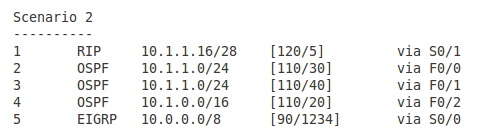
The IP packet has the destination address of 10.1.1.17. The third column on the left is the prefix learned. Which entry in the routing table (number in first column) is going to be the best in the following scenarios? Which outbound interface is going to be used?

Pic. 6 - Scenario 1.

 Pic. 7 - Scenario 2.


Pic. 8 - Scenario 3.
Pic. 9 - Scenario 4
Pic. 10 - Scenario 5

The answers to the question (all scenarios)
Scenario 1
Entry 2 is the correct answer. The egress interface is F0/0.
The router looks for the longest match in the routing table first. Entry 2 learned from RIP has the longest number of bits that are identical with the destination IP (it is the most specific). The remaining sources (OSPF and EIGRP) have fewer bits that match the destination address (they are less specific). The fact that they are more trusted does not apply here since the longest match is always preferred.

Scenario 2
Entry 1 is the correct answer. The egress interface is S0/1.
Just like in the scenario 1, the router looks for a longest match in the routing table first.
Entries 4 and 5 have 8 bits and 16 bits in common with the destination address respectively. Entries 2 and 3 have 24 bits in common. The longest match is the entry 1 having 28 networking bits that are identical with the IP address 10.1.1.17. You can check it by converting the last byte into the binary notation.

Scenario 3
Entry 2 is the correct answer. The egress interface is F0/0.
We can safely rule out the Entries 1 and 4 due to the length of network mask (not the best matches). We're left with Entries 2 and 3. Both have the same number of bits that are identical bits with the destination address (24). Both prefixes come from the same source (OSPF) and as a result of that have the same Administrative Distance value = 120. The tie breaker is going to be the metric value. Entry 2 has a cost of 30 and entry 4 has cost of 40. The lowest is the preferred one.

Scenario 4
Entry 2 is the correct answer. The egress interface is S0/0.
All five entries have the same length of prefix mask, so after longest match rule check we have five candidates.  However, entries 4 and 5 come from OSPF and have higher AD (120) than the first three entries coming from EIGRP routing protocol (90). The lower AD here is preferred. We can rule 4 and 5 out now. Again, all three of them left, have the same AD (90). The tie-breaker is the value of metric again.

Scenario 5
Entries 1 through 3 are the correct answer. The egress interfaces are S0/0, S0/1, and S0/2. The router is going to perform load balancing (traffic sharing).
We can rule out entries 4 and 5 like in the scenario 4. The remaining entries 1 through 3 come from EIGRP (AD=90) and their metrics are the same.

Lesson 30 - IPv4 Subnetting - Practice


In the previous post, I showed you three major rules used in calculating subnets. This knowledge can only be verified in practice though. Let me show you a few examples related to subnet calculations. I hope that looking at this topic from different angles is going to help you understand the concept better and feel confident when planning your IP addressing scheme. The first four questions are merely appetizers for a bigger dish: VLSM.

I am going to refer to my previous post's rules while answering the questions (rule 1, rule 2 and rule 3).

If you still do not remember the weights of all bits, you may consider using this little aid presented below (pic. 1) while calculating subnets, and converting binary network masks into decimal values.

Pic. 1- Subnet Calculation Aid.

This tool is useful before you remember all the weights from left to right and right to left.
Pic. 2 - Example of Subnet Binary-to-Decimal Conversion.

Question 1
Given the prefix 192.168.1.0/24, what should be the length of subnet mask allowing up to 9 subnets?

Answer 1
The address belongs to the class C and uses its default network mask. That leaves us with 8 bits to play with (the last byte). Before we change anything, our address and network mask converted into the binary notation look like shown below (pic. 3).
Pic. 3 - 192.168.1.0/24 in Binary.

In order to create 9 subnets we must extend the existing length of the network mask by 4 bits which allows up to 16 subnets (use calculation aid in pic. 1). If I tried to extend it by 3 bits only, the maximum subnets allowed would be only 8 subnets (rule 2 in lesson 29). So, I must use 4 bits and the result is: 192.168.1.0/28 (192.168.1.0 255.255.255.240).

Pic. 4 - The Answer to Question 1

Question 2
Given the host address 192.168.1.177/29, what are the subnet and broadcast addresses?

Answer 2
In order to determine the subnet and broadcast address of the subnet of this host address, we must look at the length of the network mask first. It is 29 bits (24+5). This tells us that the last byte of the address has 5 bits masked (subnet bits) and 3 bits unmasked (host bits). It is a good idea to look at the the last byte of the address (177) with its network mask using binary notation. Pic. 5 below shows you this clearly.
Pic. 5 - 192.168.1.177/29 in Binary.
Since we must determine the the subnet in which the host resides (177 = 10110001), the host portion of the prefix (host bits reside in the last byte) must all be set to '0'. The byte value with the host zeroed is the address of the subnet (rule 1 pkt.1 in lesson 29). This is the result:

Pic. 6 - Host Bits Zeroed = Subnet Address.

The second part of the question relates to the broadcast address of the subnet. As you remember, in order to obtain the broadcast address, you must put '1' on all host bits of the subnet/network. The subnet has already been determined (pic. 6), so let's put '1' on all bits of the host portion:
.10110111
.10110000 = 176 <- subnet address
..00000111 = 7 <- host bits set to '1'

In decimal it is: 176 + 7 = 183
The broadcast address is: 183.

The below picture illustrates it using binary numbers.

Pic. 7 - Host Bits Set to '1' = Broadcast Address.

Question 3
Given the  prefix 172.16.0.0/17, how many subnets can you create?

Answer3
This is a bit tricky isn't it? In order to answer this question, you don't need any calculator, paper or pen. You must trust the rule 2 in lesson 29. The address and its network mask (called prefix) converted into binary look like presented below:
Pic. 8 - The Number of Subnets for 172.16.0.0/17

As you see the number of bits we have extended the class B address is: 1. So, the number of subnets we can create with it is: 2 subnets, since this subnet bit can be either 1 or 0.
Pic. 9 - Questions 3 Answer

Question 4
What length of network mask would be the most optimal for router's point-to-point connection?

Answer 4
The key to this question is to understand that point-to-point connection needs only 2 host addresses (two points that are connected together). Knowing this, the rest is a piece of cake. We use rule 3 inlesson 29 to determine the length of the network mask that allows 2 host addresses. Check out the picture 10.
Pic. 10 - Calculating Point-to-Point Connection Host Addresses.
If you count ones above the optimal network mask for point-to-point connection is /30. The decimal value is: 255.255.255.252.
Question 5 - Variable Length Subnet Masking (VLSM)
It's time for a big one. Given the topology (pic. 11), calculate IP addresses for each subnet trying to optimize them according the host address requirements. The IP address you should use to create subnets is: 192.168.1.0/24. The number of host addresses in the subnets are as follows:
Subnet 1 = 46 host addresses
Subnet 2 = 16 host addresses
Subnet 3 = 10 host addresses
Subnet 4 = 2 host addresses
Subnet 5 = 2 host addresses

Pic. 11 - VLSM Topology.

Icons designed by: Andrzej Szoblik - http://www.newo.pl

As always, if you know the rules and the method, it is going to be easy thing to do. The rules have been discussed in lesson 29, so let me go about this kind of task now.


NOTICE!
If your design looks similar to mine (optimizing addresses to the number of host required) you muststart the calculation with the largest number of host addresses requirement and work your way down to the least number of host addresses.


This is one of the many methods available. It helps quickly calculate all subnet ranges without using calculator (pen and a piece of paper should do).

Step 1
Determine the length of the network mask for each subnet in question. Keep in mind we focus in on the last byte of IP address 192.168.1.0 (8 bits).
The first three bytes do not change!

Subnet 1 = 46 Host Addresses

In order to allocate 46 addresses we must use 6 host bits. Why? 5 bits will not be enough as 2 raised to the power of 5 is 32. Also, we must decrement two addresses for subnet and broadcast addresses. So using 5 bits would give you only 30 host addresses. Here we go with 6 bits then:

Pic. 12 - Subnet 1 in Binary.
Subnet 2 = 16 Host Addresses

We must repeat the same math for the remaining subnets.  How many host bits to allocate for 16 hosts (subnet 2)? We must use 5 bits. In case we wanted to use only 4 host bits, the maximum number of hosts is 14 (16 - 2).
Pic. 13 - Subnet 2 in Binary

Subnet 3 = 10 Host Addresses

We continue using the same logic.

Pic. 14 - Subnet 3 in Binary.
 Subnet 4 and 5 = 2 Host Addresses Each

On point-to-point links only 2 host addresses area needed. The most optimal network mask is /30(30 bits).

Pic. 15 - Subnet 4 and 5 in Binary.
Step 2
Now, that we know the length of network mask for each subnet, we can start calculating the IP address ranges. 

The subnet 1 address is: 192.168.1.0/26.

The value of the lowest bit in the network mask is going to be our increment used to calculate the next available subnet address. With /26 the increment value is 64 (pic. 16).
So, if we add the increment to the last byte, we get the number of our next available subnet address:
192.168.1.0 + 64 = 192.168.1.64.

From there, this next subnet address (value) - 1 is the broadcast of our current subnet:
192.168.1.64 - 1 = 192.168.1.63 (current broadcast address)
Current subnet value + 1 = the first host address:
192.168.1.0 + 1 = 192.168.1.1 (first host address of current subnet)

Current broadcast address - 1 = the last host's address:
192.168.1.63 - 1 = 192.168.1.62 (last host address of current subnet).

Look at the below pictures which illustrate this method.

Pic. 16 - Subnet 1 - IP addresses


Pic. 17 - Subnet 2 - IP addresses

Pic. 18 - Subnet 3 - IP addresses

 Pic. 19 - Subnet 4 - IP addresses

Pic. 20 - Subnet 5 - IP addresses

Now, we're ready to start talking about routing. In my next post, I will talk about a router, its functions,and  basic operation. From there, we'll start exploring routing protocols.