In this post, I'm going to present the commands and verification steps with regards to OSPF implementation in a single area. Configuration will also include the authentication of OSPF packets.
If you want to go fancy with OSPF the configuration can be quite challenging. Configuring basic OSPF in a single area is very simple though. There are two basic steps required:

OSPF Basic Configuration
The commands which enables OSPF on an interface can look like the below.

 Look at the Pic. 2 again. According to the network statement, OSPF will be enabled on F1/0 and S0/1 of R1 (pic. 1).
What network statement could we use in order to enable OSPF on s0/1 interface but not on F1/0?
I can give you a couple of examples. Remember that wildcard mask will use '0s' to check bits in the address and '1s' will ignore them.
Example 1
This way the wildcard bits are going to check if there are any interfaces which use IP addresses according to 10.1.13.x (where x is any number). These will be OSPF-enabled.
Example 2
The second example will enable OSPF on the interface that has the EXACT IP address 10.1.13.1. The wildcard bits consists of all '0s' so ALL the corresponding bits in the IP address used must match in order for the interface to be running OSPF protocol.
As you already know, the moment we enable OSPF on an interface, the routing process begins to send the 'hello' packets trying to discover the neighbor(s). If they are discovered the system begins to check parameters in the OSPF header and hello packet. If they agree on the mandatory fields (hello/dead intervale etc.) the are going through several phases to finally synchronize their LSDBs.
Of course, the network statement with wildcard mask does not influence what network mask is going to be advertised along with the IP address. OSPF, being a classless routing protocol, will advertise their networks/subnets as per configuration on the interfaces.
So, let's configure OSPF as per topology diagram (pic. 1) and observe the process of reaching the FULL state (adjacency) using the debug. I will use the most specific wildard mask here but you already know there are a lot of options available to start OSPF on the interfaces.
R1 Configuration:
R3 Configuration:
Now, here's the output of the debug statement on R3. Pay attention to the highlighted words and compare them with the OSPF Neighbor State Machine (lesson 38 in the archive of this blog).
 Notice, that it is a point-to-point network, so there is no election of DR and BDR roles.
As part of practical exercise, try to use the same debug in you lab on routers connected using broadcast (Ethernet) links. Watch for DR/BDR election.
OSPF Verification Commands
It is important to be able to perform some basic verification steps. Here are the commands that you will use most often.
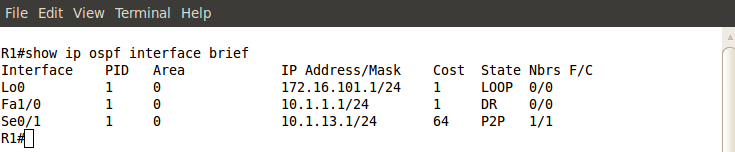
First, let's check if our network statement was correct (OSPF is enabled on the appropriate interfaces).

You can also see a detailed output which shows more information with regards to OSPF running on an interface. Check it out.

Then, I want to make sure that R1 is in FULL state with R3. Here's my command:


Notice that both R1 and R3 advertise four links. The loopback0, F1/0, and S0/1 which counts as two links (point-to-point interfaces are advertised as two: the IP address of the next hop and the subnet/network IP).
And finally, the content of OSPF routing table:

OSPF Authentication
As part of implementation we can authenticate OSPF packets to prevent some rouge routers joining our OSPF domain. If someone configures and plugs in the router, it won't become adjacent with others in the domain unless the right method and password are used.
There are two methods to authenticate OSPF packets:
Let's start with Simple Password method.
Method 1 (password must match on both routers; here: S3cr3t)
Method 2
The first command enables OSPF authentication using Simple Password method (area 0 authentication or ip ospf authentication)
The second command specifies the password that is going to be used (ip ospf authentication-key)
In the first method, OSPF authentication is enabled on ALL interfaces configured to operate in area 0. The second method allows more control as to which interfaces will be sending authenticated OSPF packets.

Method 2
Both the password (here: S3cr3t) and the key number (here: 1) must match between the neighbors.
You might try out the following two commands and see what they show:
The next post is going to be the last one in the OSPF series. We are going to configure OSPF in the more complex topology as well as use some troubleshooting techniques to fix the common configuration issues.
If you want to go fancy with OSPF the configuration can be quite challenging. Configuring basic OSPF in a single area is very simple though. There are two basic steps required:
- Enable OSPF in the 'config' mode.
- Instruct the OSPF process which interfaces should be enabled for OSPF and in which areas the links should operate.
Pic. 1 - Topology Diagram.

Icons designed by: Andrzej Szoblik - http://www.newo.pl
OSPF Basic Configuration
The commands which enables OSPF on an interface can look like the below.
Pic. 2 - Example of OSPF Configuration.

router ospf 1 - This command starts the OSPF process 1 on R1.
network 10.1.0.0 0.0.255.2555 area 0 - This statement enables OSPF process on all interfaces which IP addresses are 10.1.x.x (where x.x can be any number as the last two bytes are not checked by the wildcard mask).
What is the wildcard mask in the above statement?
Wildcard mask is an inversed network mask. The bits in the wildcard mask which are set to '0' will check the corresponding bits in the IP address. The bits in the wildcard mask which are set to '1' will ignore the corresponding bits in the IP address.
Pic. 3 - OSPF Wildcard Mask.

What network statement could we use in order to enable OSPF on s0/1 interface but not on F1/0?
I can give you a couple of examples. Remember that wildcard mask will use '0s' to check bits in the address and '1s' will ignore them.
Example 1
R1(config)#router ospf 1
R1(config-router)#network 10.1.13.0 0.0.0.255 area 0
This way the wildcard bits are going to check if there are any interfaces which use IP addresses according to 10.1.13.x (where x is any number). These will be OSPF-enabled.
Example 2
R1(config)#router ospf 1
R1(config-router)#network 10.1.13.1 0.0.0.0 area 0
The second example will enable OSPF on the interface that has the EXACT IP address 10.1.13.1. The wildcard bits consists of all '0s' so ALL the corresponding bits in the IP address used must match in order for the interface to be running OSPF protocol.
As you already know, the moment we enable OSPF on an interface, the routing process begins to send the 'hello' packets trying to discover the neighbor(s). If they are discovered the system begins to check parameters in the OSPF header and hello packet. If they agree on the mandatory fields (hello/dead intervale etc.) the are going through several phases to finally synchronize their LSDBs.
Of course, the network statement with wildcard mask does not influence what network mask is going to be advertised along with the IP address. OSPF, being a classless routing protocol, will advertise their networks/subnets as per configuration on the interfaces.
So, let's configure OSPF as per topology diagram (pic. 1) and observe the process of reaching the FULL state (adjacency) using the debug. I will use the most specific wildard mask here but you already know there are a lot of options available to start OSPF on the interfaces.
R1 Configuration:
R1(config)#router ospf 1
R1(config-router)#network 10.1.1.1 0.0.0.0 area 0
R1(config-router)#network 10.1.13.1 0.0.0.0 area 0
R1(config-router)#network 172.16.101.1 0.0.0.0 area 0
R1(config-router)#
R3 Configuration:
R3(config)#router ospf 1
R3(config-router)#network 10.1.3.3 0.0.0.0 area 0
R3(config-router)#network 10.1.13.3 0.0.0.0 area 0
R3(config-rotuer)#network 172.16.103.3 0.0.0.0 area 0
R3(config-router)#
Now, here's the output of the debug statement on R3. Pay attention to the highlighted words and compare them with the OSPF Neighbor State Machine (lesson 38 in the archive of this blog).
Pic. 4 - Debug IP OSPF Events on R3.

As part of practical exercise, try to use the same debug in you lab on routers connected using broadcast (Ethernet) links. Watch for DR/BDR election.
OSPF Verification Commands
It is important to be able to perform some basic verification steps. Here are the commands that you will use most often.
First, let's check if our network statement was correct (OSPF is enabled on the appropriate interfaces).
Pic. 5 - OSPF-enabled Interfaces.
Pic. 6 - OSPF-enabled Interface Detailed Output (Fa1/0).

Then, I want to make sure that R1 is in FULL state with R3. Here's my command:
Pic. 7 - OSPF Neighbor Check.

Two more commands will be useful as well. First one showing the brief output of LSDB (more detailed output is beyond the scope of this tutorial).
Pic. 8 - OSPF Database.

And finally, the content of OSPF routing table:
Pic. 9 - OSPF Routing Table.

As part of implementation we can authenticate OSPF packets to prevent some rouge routers joining our OSPF domain. If someone configures and plugs in the router, it won't become adjacent with others in the domain unless the right method and password are used.
There are two methods to authenticate OSPF packets:
- Simple Password - The password is sent in the clear text format.
- MD5 - The password is not sent at all. The digest is created using the shared password between neighbors.
Let's start with Simple Password method.
Method 1 (password must match on both routers; here: S3cr3t)
R1(config)#router ospf 1
R1(config-router)#area 0 authentication
R1(config-router)#exit
R1(config)#interface serial0/1
R1(config-if)#ip ospf authentication-key S3cr3t
Method 2
R1(config)#interface serial0/1
R1(config-if)#ip ospf authentication
R1(config-if)#ip ospf authentication-key S3cr3t
R1(config-if)#
The first command enables OSPF authentication using Simple Password method (area 0 authentication or ip ospf authentication)
The second command specifies the password that is going to be used (ip ospf authentication-key)
In the first method, OSPF authentication is enabled on ALL interfaces configured to operate in area 0. The second method allows more control as to which interfaces will be sending authenticated OSPF packets.
Pic. 10 - Simple Password Authentication Enabled.

MD5 method can also be configured in two ways.
Method 1 (password must match on both routers; here: S3cr3t)
R1(config)#router ospf 1
R1(config-router)#area 0 authentication message-digest
R1(config-router)#exit
R1(config)#interface serial0/1
R1(config-if)#ip ospf message-digest-key 1 md5 S3cr3t
Method 2
R1(config)#interface serial0/1
R1(config-if)#ip ospf authentication message-digest
R1(config-if)#ip ospf message-digest-key 1 md5 S3cr3t
R1(config-if)#
Both the password (here: S3cr3t) and the key number (here: 1) must match between the neighbors.
Use: show ip ospf int s0/1 to check MD5 authentication.
You might try out the following two commands and see what they show:
R1#show ip protocols
R1#show ip ospf
The next post is going to be the last one in the OSPF series. We are going to configure OSPF in the more complex topology as well as use some troubleshooting techniques to fix the common configuration issues.

