Showing posts with label destination. Show all posts

Mar 13, 2013

Lesson 52 - Network Address Translation Part 2


NAT Principles in a Nutshell
Now, that you realize there are not enough addresses for all devices in the global network, we can proceed with the general principles behind NAT.

The idea is quite simple when you think about it. The role of the edge router (the one that connects our private network to ISP) is to replace the original, source address in the IP header (private) with the one that is globally unique.

When the packet comes back, the edge router must have enough information to replace the globally unique address used (which now is the destination address) with the same one that was used by the sender originally (private).

NAT Principles - Detailed Explanation
Using our proper terminology, when the IP packet enters the router's inside interface (connected to the LAN), and is sent out the outside interface (connected to the Internet), it removes the inside local address (private, e.g. 192.168.1.1), makes a note what it did in the so called NAT table, and inserts the inside global address (public) in the IP header instead.

So for instance, the original source 192.168.1.1 becomes 86.46.1.10 when the packet is sent towards the Internet (apologies if I use somebody's real IP address here) .

Then, when the destination host sends the reply back to the original sender, this 86.46.1.10 (former source) becomes the destination address. Our edge router receives it on its 'outside interface'. Since, the outbound interface is now our 'inside interface' the router will need to find the appropriate entry in the NAT table which will allow it to identify the original sender's address (our 192.168.1.1). Its address will be now inserted in the destination field of IP header so the packet will be sent to the appropriate host originating this transmission. Check the step-by-step procedure below to see that more clearly.

Step 1
PC (Src=192.168.1.1) is sending packet towards Cisco web server (Dst=72.163.4.161). Since, the destination is not on the same network, the packet is sent towards the default gateway (MAC address of the router's F0/0). If you have problems with this, try to look back at the lessons about TCP/IP traffic flow.

Step 2
The router R1 receives the frame, checks the MAC address and realizes it is the destination for this Layer 2 frame (its MAC address shows in the destination field of the Ethernet header). Layer 2 frame is stripped off and the IP header is read. The destination IP (72.163.4.161) is not listed in the routing table, but the router has a default route (0.0.0.0/0) which tells it to send it to the ISP's router (here:R2). The packet is moved to the outbound interface (S1/0).

Now comes the tricky part. Both interfaces have been assigned special roles in NAT configuration. The interface F0/0 is configured as 'nat inside' which tells the router that packets sourced here belong to the 'inside local' group of addresses (candidates for translation). And the S1/0 interface is configured as 'nat outside'. This interface cannot send packets out with their original 'inside local' numbers (private addresses defined in RFC 1918). The router must perform the translation (address replacement) as per Step 3.

Step 3
R1 is removing 192.168.1.1 address from the IP header (source), and inserts 'inside global' address given to us by our ISP (for example: 86.46.1.10). You're probably waving your hands right now in protest saying: but my ISP does not give me many addresses. Stick with me for now, I will address this issue in my next post. For now, let's just assume that our ISP is generous and gives us a whole bunch of public IP addresses.

After removing 192.168.1.1 and replacing it with 86.46.1.10, the packet is sent out towards its destination (72.163.4.161). R1 creates a special entry in the NAT Table which will allow it to replace it back to 192.168.1.1 when the packet is sent back from www.cisco.com (72.163.4.161). Look at this action below:

Pic. 1 - Inside Local Address Replaced with Inside Global.
Icons designed by: Andrzej Szoblik - http://www.newo.pl

Step 4
The Cisco web server (72.163.4.161) is replying back to the sender. So, the IP header has the following addresses:
Src = 72.163.4.161
Dst = 86.46.1.10

The routers on the Internet send it back to our ISP (don't ask how it's done), which in turn, sends this towards S1/0 interface. At this stage, tTake this action for granted. The packet arrives on the 'nat outside' interface of R1 (S1/0). This is where the router is going to look into the NAT table, that should have the proper entry created before, allowing it to remove 86.46.1.10 and inserting the previously used address (192.168.1.1). This action allows to send this packet out its 'nat inside' interface (F0/0) back to the host which originated this transmission and expects to receive the reply.

After translation, the header looks as follows:
Src = 72.163.4.161
Dst = 192.168.1.1

The PC receives the reply packet from 72.168.4.161 as expected.

Pic. 2 - Inside Global Replaced with Inside Local.
Icons designed by: Andrzej Szoblik - http://www.newo.pl

If you have many public addresses (inside global) you can configure this type of translation using two methods:

  • Static Translation - one-to-one translation (one inside local is represented by the same inside global address). This allows 24/7 access to that computer (e.g. www, ftp, smtp, etc.) since the entry never ages out.
  • Dynamic Translation - computers can use the public addresses from the pool of available ones. Then, after the transmission ends and the entry ages out, this public (inside global) address is sent back to the pool and other computer can use it. There is not permanent one-to-one translation using this method.
The problem is that in 99.999% cases, ISP only gives you a one public address which is applied on the router's interface facing the Internet ('nat outside'). How does NAT handles this problem?

In such situations we use Port Address Translation (Cisco also calls this method NAT overload). This method I leave for my next post.

Lesson 49 - Packet Filtering with Extended ACLs


This post I start with presenting solution to the Task 2 I left unanswered in the lesson 49.

Task 2
Configure an IP standard ACL that denies packets coming from the host 172.31.123.3 going towards 192.168.5.0/24. Traffic from other sources should be allowed. 

Again, we use the standard IP ACL here, which is going to be applied on R5. Here goes:

R5 Configuration:

!
In the global config 
!
access-list 1 deny host 172.31.123.3
access-list 1 permit any
!
Enter the the incoming interface and apply the access-list
!
interface serial0/2
 ip access-group 1 in
!

Notice!

  • access-list 1 - ACL numbers 1-99 are IP standard ACLs (check source of the packets only.
  • host 172.31.123.3 - this keyword is an alias for: 172.16.123.3 0.0.0.0. It is a source address of the packets being inspected.
  • any - this keyword is an alias for: 0.0.0.0 255.255.255.255 - any source here.
I hope your answers were correct. Now is the time to learn Extended ACLs.

First, look at the syntax you see in Cisco documentation:

Pic. 1 - Extended ACL Syntax.

If you go like: 'OMG!' do not worry because you do not have to use all these keywords.

The options we are going to use can be presented as follows:

Pic. 2 - Extended ACL Common Syntax.
It looks a bit more convoluted but do not worry because in time you will feel quite confident with it. Your best friend is help '?' which is going to show you what options and arguments are required.

The best way to explain the syntax you need to get familiar with is to use an example and try to de-construct it. So, let's look at our topology one more time and create the following filter:

Task 1
Deny telnet sessions coming from 192.168.4.0/24 destined to 172.31.3.0/28 and 172.31.3.16/28. All other traffic should be allowed.

Pic. 3 - Topology.
Icons designed by: Andrzej Szoblik - http://www.newo.pl

Which ACL type should we use?
Since, we are very specific in terms of which protocols we want to deny, we must use Extended ACL. The standard ACL can only match on the source IP address, permitting or denying all protocols the packet is carrying.

Which router/interface should we apply the ACL on?
Our topology clearly shows that R3 has three different interfaces with three different addresses. So, we have two options here:

  • We can configure an Extended ACL on R4 FastEthernet 1/0 interface in the inbound direction (close to the source as per ACL guideline)
  • We can configure an Extended ACL on R4 Serial0/2 in the outbound direction.
  • Alternatively, we can apply an Extended ACL on R3 FastEthernet1/0 (inbound).
I'm going to chose the option suggested by the ACL guide lines: as close to the source as possible.

Let's read the task again:


Task 1

Deny telnet sessions coming from 192.168.4.0/24 destined to 172.31.3.0/28 and 172.31.3.16/28. All other traffic should be allowed.

Here's one way to configure this:

R4 Configuration:

!
In the global 'config' mode the statements are:
!
access-list 100 deny tcp 192.168.4.0 0.0.0.255 172.31.3.0 0.0.0.15 eq 23
access-list 100 deny tcp 192.168.4.0 0.0.0.255 172.31.3.16 0.0.0.15 eq 23
access-list 100 permit ip any any
!
Apply the ACL on the interface
!
interface FastEthernet 1/0
  ip access-group 100 in
!

Three lines that 'deny' traffic are similar. Let's dissect its syntax:

access-list 100 deny tcp 192.168.4.0 0.0.0.255 172.31.3.0 0.0.0.15 eq 23

  • access-list 100 - The extended ACL (numbers 100-199)
  • deny - condition (either 'deny' or 'permit' are allowed)
  • tcp - layer 3 or 4 protocol (such as: ipicmptcpudpripeigrp etc.)
  • 192.168.4.0 - source IP address
  • 0.0.0.255 - source wildcard mask (inversed mask)
  • 172.31.3.0 - destination IP address
  • 0.0.0.15 - destination wildcard mask (inversed mask)
  • eq - operator: eq (equal), lt (less than), gt (greater than), range
  • 23 - destination port (telnet)
Notice!
After source wildcard there is no source port. This means that the source port is not inspected at all (disregarded).

In the next post I'm going to show you few examples of extended ACL which should reinforce your study

Mar 12, 2013

Lesson 32 - Route Selection Process Demistified


It is imperative to know how a router selects the best path to some destination network/subnets if it has more than one to choose from. At least if you are serious about learning the routing principles. In this post I'm going to show you the algorithm a router uses to discriminate between multiple paths to the same destination.

A router can learn the routes to remote networks and subnets using manual instructions or by means of configuring routing protocols. This way routers learn how to reach destination networks/subnets dynamically. This post's primary focus is about Interior Gateway Protocols(IGPs) such as: RIP, OSPF, EIGRP. The only Exterior Gateway Protocol (EGP) we use nowadays is called BGP. It uses a bit more complex decision making process and is beyond the scope of this tutorial. In the future I am going to talk about it in more detail in the workbooks I plan to post in the future.

First things first. There are three terms I need to define in order to explain the process of selecting the best route. These are:

  1. The Longest Match Rule
  2. Administrative Distance
  3. Metric
The Longest Match Rule
In the previous post I showed you an example of routing table with a brief explanation about what each column in the output represented. Pic. 1 is the graphic equivalent of it.

When a router receives a packet, while processing the header, it is the DESTINATION IP address that is compared with the entries in the routing table in order to determine the next step. This next step is to find the egress (outbound) interface and the address of the next device to send the packet to. This form of routing is known as the destination-based routing. The process of comparing the destination IP with the prefixes int the routing table is done bit by bit (yes, routers see IP addresses in the binary notation). The entry that has the longest number of network bits that match the IP destination address is always the best match (best path). This is always the FIRST thing a router checks.

If there is ONLY ONE best match, a router has a simple task to do. It moves the packet to the outbound interface (egress) and encapsulates the packet in the layer 2 header according to the technology/protocol that is used on the outbound interface (Ethernet, PPP, HDCL, Frame-Relay etc.). Then, the frame is converted to bits and placed onto the wire/fiber optic cable.


NOTICE!
If the outbound interface is a multi-access interface (such as Ethernet, Frame-Relay, ATM etc.), the router must know the layer 2 identifier of the next-hop device (layer 3 to layer 2 address resolution). For instance, in case the outbound interface is Ethernet, the MAC address of the next-hop device must be in the router's arp cache (if not found, the arp query is sent). In case, the egress interface is of a point-to-point type (subinterface point-to-point or protocol such as PPP, HDLC etc. is used), there is NO layer 3 to layer 2 resolution being performed. The packet is simply encapsulated in layer 2 frame sent out that interface.


Let's consider the example depicted in pic. 1.

Pic. 1 - The Longest Match Rule.

In this example the router receives an IP packet. The DESTINATION Address in the packet is172.31.1.33. The router is going to compare this address (bit by bit), with the prefixes (address/network-mask) in the routing table presented, trying to find the closest match (the number of bits that are the same). The entry that is the best match will give the router instructions as to what is the address of the next-hop device (here another router) and the outbound interface.

Let's play the router's game and compare all the entries with the DESTINATION IP address of the packet.

There are three candidate entries pointing to three different next-hop routers and three different outbound interfaces (pic. 1). The pic. 2 shows these numbers in the binary notation.

Pic. 2 - Destination IP Address Comparison.

Clearly, when converted into binary, the first entry shows the best match . The number of identical bits between the packet's destination address and router's knowledge about the subnet is 28 identical bits (highlighted in red). The second entry has only 24 identical bits, and the third one, only 16 bits match the destination IP address (class B network address). That is why the egress interface for the packet towards 172.31.1.33 is FastEthernet0/0 (pic. 1).

So far, we have only dealt with the situation in which there is a SINGLE best match. What if there are more than one entries (paths available) in the routing table with the EXACT same longest match?

There are two other parameters a router uses to break the tie:

  1. Administrative Distance
  2. Metric
Administrative Distance
There are the situations that your router(s) may use more than one source of information. Not that you create such situation on purpose. You are better off using one protocol (e.g. OSPF), but reality bites and sometimes you have to support more than one routing protocol in the same routing domain. In such situations your router may receive the same prefix(es) from different sources. As a result of that multiple sources (RIP, OSPF, EIGRP etc.) provider the router with the EXACT same prefix (address/network-mask).

In order to deal with situations like this, Cisco have created a ranking which assign the protocols (sources of information) different levels of "trustworthiness" (if that's a word). This level of "believability" is expressed with the arbitrarily allocated value that is given to different sources of information. This parameter is called: Administrative Distance (or just 'distance'). The LOWER the value of AD is, the more trusted the source of information is going to be.

Consider the pic. 3. The router receives EXACT same prefix (192.168.1.0/24) from two different sources: RIP and OSPF. Since this is going to cause an issue as to which one is better, AD is going to break the tie. OSPF is more trusted than RIP as it has lower value of Administrative Distance assigned to it (110) compared to RIP's (120).

There are many reasons why RIP is less trusted source than OSPF, but explaining it in detail is beyond of the scope of this post. Needless to say, if you do not like Cisco arbitrarily set values, there are ways of changing them. The commands are different for different protocols, and when we get to advanced topics (hopefully), I'm going to show them to you.

Pic. 3 - Advertisement Come from Different Sources (Protocols).

Icons designed by: Andrzej Szoblik - http://www.newo.pl

I have included a few AD values for the most often used protocols to get you going. For more information on that go to Cisco web site. Of course the best way of finding the values is to use my favorite search engine: google ;).

Metric
Another situations that might put a router in a difficult position regarding which path is the best occurs when there are multiple longest match entries in the routing table, coming from the same source. Or more accurately speaking, there are multiple best matches (EXACT prefixes) having the same value of Administrative Distance (AD).

In such situations, the tie-breaker is going to be the LOWEST value of the METRIC.

A metric is the value calculated for each prefix and expresses, for the lack of better word, how far the destination is. The lower the value, the more preferred the path is.

Keep in mind, that the type of metric routing protocols use (the way they calculate it) is different between them and totally INCOMPATIBLE. They use different ways and factors to calculate their metric.

Just to give you a few examples, RIP uses the concept of hop-count. The number (metric) tells the router how many routers the packet must traverse before it reaches the destination.

OSPF on the other hand, uses the cost as its metric. It is calculated based on the bandwidth of the interfaces (links) in the path. This way, its metric is far more sophisticated and more suitable for our networks compared to RIP.

As you see it is not the coincidence that OSPF is more trusted source of information compared to RIP.

Consider the following example (pic. 4).

Pic. 4 - An Example of Metric Types.
Icons designed by: Andrzej Szoblik - http://www.newo.pl

If in your design you decided to use RIP in the above topology, the router A, would choose the best path towards 10.2.2.0/24 through router B. This is because the metric used by RIP takes into consideration the number of routers the packet has to traverse, and nothing else. The path throughrouter B is better (1 hop), as opposed to the path through routers CDB (3 hops). RIP does not factor in the bandwidth of the links in the path.

If you chose to use OSPF instead, the number of hops (routers the packet is going to go through) is irrelevant. OSPF makes forwarding decisions based on the bandwidth available in the paths. This way, OSPF prefers path through routers CDB, rather than through router B (much faster links available).

More on the topic of metrics in the upcoming posts. Now, that you have learned about the factors that help routers determine the best path, you are ready to take a look at the algorithm.

  1. Prefer the path with the longest match entry in the routing table (irrespective of the metric or AD).
  2. In case there are multiple best matches available, check the AD value (if they come from the same source). Choose the source of information with the lowest AD. 
  3. If the best match prefixes (more than one) come from the source with the same AD, choose the lowest metric number.
The same order of operation is presented in the pic. 5.


NOTICE!
When considering Border Gateway Protocol, its metric is very complex (not a single number like all Interior Gateway Protocols tend to use). As a result of that, the rules of finding the best route are also more complex and are beyond the scope of this post.


Pic. 5 - Route Selection Process.

Traffic Sharing
One last scenario. What if a router receives more than one exact longest match prefixes that have the same values of AD and the metric?

All of them are the best candidates and the router performs load sharing (load balancing) using all of the egress interfaces that are the best. Of course, whether it is per-packet, or per flow load-balancing depends on the switching engine configuration of your router.

I hope you have caught the idea by now. Check yourself by answering the following question. You will find the answers for all scenarios presented at the bottom of this post.

Practical Question
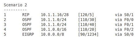
The IP packet has the destination address of 10.1.1.17. The third column on the left is the prefix learned. Which entry in the routing table (number in first column) is going to be the best in the following scenarios? Which outbound interface is going to be used?

Pic. 6 - Scenario 1.

 Pic. 7 - Scenario 2.


Pic. 8 - Scenario 3.
Pic. 9 - Scenario 4
Pic. 10 - Scenario 5

The answers to the question (all scenarios)
Scenario 1
Entry 2 is the correct answer. The egress interface is F0/0.
The router looks for the longest match in the routing table first. Entry 2 learned from RIP has the longest number of bits that are identical with the destination IP (it is the most specific). The remaining sources (OSPF and EIGRP) have fewer bits that match the destination address (they are less specific). The fact that they are more trusted does not apply here since the longest match is always preferred.

Scenario 2
Entry 1 is the correct answer. The egress interface is S0/1.
Just like in the scenario 1, the router looks for a longest match in the routing table first.
Entries 4 and 5 have 8 bits and 16 bits in common with the destination address respectively. Entries 2 and 3 have 24 bits in common. The longest match is the entry 1 having 28 networking bits that are identical with the IP address 10.1.1.17. You can check it by converting the last byte into the binary notation.

Scenario 3
Entry 2 is the correct answer. The egress interface is F0/0.
We can safely rule out the Entries 1 and 4 due to the length of network mask (not the best matches). We're left with Entries 2 and 3. Both have the same number of bits that are identical bits with the destination address (24). Both prefixes come from the same source (OSPF) and as a result of that have the same Administrative Distance value = 120. The tie breaker is going to be the metric value. Entry 2 has a cost of 30 and entry 4 has cost of 40. The lowest is the preferred one.

Scenario 4
Entry 2 is the correct answer. The egress interface is S0/0.
All five entries have the same length of prefix mask, so after longest match rule check we have five candidates.  However, entries 4 and 5 come from OSPF and have higher AD (120) than the first three entries coming from EIGRP routing protocol (90). The lower AD here is preferred. We can rule 4 and 5 out now. Again, all three of them left, have the same AD (90). The tie-breaker is the value of metric again.

Scenario 5
Entries 1 through 3 are the correct answer. The egress interfaces are S0/0, S0/1, and S0/2. The router is going to perform load balancing (traffic sharing).
We can rule out entries 4 and 5 like in the scenario 4. The remaining entries 1 through 3 come from EIGRP (AD=90) and their metrics are the same.

Lesson 31 - What is a Router?


We take a lot of things for granted. When it comes to technologies it is not necessarily the best idea. The point is to understand. That is why I am going to start my routing section with fundamentals. Knowing them will allow you to learn more advanced topics on your own later. Make sure you are familiar with my previous posts related to binary numbers and IP addressing before you read this and upcoming ones.

Probably the most appropriate question to start with would be ...

What is a router?
A router is a specialized computer which can connect multiple networks to allow exchange of packets between them. Since a router uses IP header information (layer 3 protocol data unit), to transmit the packets between networks, this ability makes it a layer 3 device. Like switches, routers build a special database which serves as the source of information on what to do with incoming packets. This database is formally called Routing Information Base (RIB). But most often people call it a routing table. How a router constructs a routing table and maintains information in it, will be the topics of quite a few upcoming posts.

A router is in many ways similar to a regular PC. It has RAM and ROM memory chips as well as CPU and motherboard etc. But instead of using hard drive, it uses a flash memory to store files such as the operating system (IOS). Also, what makes it distinct, the operating system and hardware are optimized for fast packet transmissions. Typically the router uses at least two interfaces but more often than not, it has a greater number of them. Cisco operating system is called InternetworkOperating System (IOS). The same name is given to OS used by many Cisco Catalyst switches. Although some of them may also use CatOS.

There is a great variety of interfaces routers can use. For instance, they can connect few Ethernet networks together, but also Ethernet with Wide Area Networks (WANs) such as ATM, Frame-Relay, X.25, ISDN, Broadband etc.

Router Functions
In order for the routers to connect multiple layer 3 networks together, they must be able to do the following:

  • Learn which networks/subnets are available
  • In case there are multiple paths, choose the the best one
  • Keep (routing table) must be up-to-date
  • Translate layer 2 headers (disparate network connections)
  • Keep loop-free paths
  • Make forwarding decisions based on layer 3 headers
Routing is primarily based on hop-by-hop paradigm. This means that if there are multiple routers in the path, a router must find the outbound interface and forward the packet to a next hop router. A router could not care less as to what happens to the packet after it has been expedited.

In order to find the outgoing interface an IP destination address of a packet and a routing table are used. The process whereby destination IP address is the key information to find the outbound interface for a packet is called destination-based routing. However, it is possible to influence that decision making process and choose other criteria such as source of IP transmission, size of the packet, importance of the packet in relation to others or some other parameters rather than destination IP address. When used it is referred to as the traffic engineering. For now though, I am going to focus in on the default behavior.

Before I describe the router's principles of operation, I must make sure we are on the same page with the fundamentals related to the traffic flow.

Let's recall what happens with the packets sent between computers residing in different networks. I will use a simple topology (pic. 1) to review a few facts. Please, get familiar with the picture below first. Pay a special attention to the three headers depicted and numbers in green circles. The numbers refer to the steps below. Of course, this is only a ten thousand foot view of what happens here. Before we jump into the deep water we need to warm up a bit by looking at the process from a high perspective.

Pic. 1 - Traffic Flow and Layer 2/layer 3 Encapsulation/Dencapsulation
Icons designed by: Andrzej Szoblik - http://www.newo.pl

The numbers in green circles mark the important points of the traffic sent from PC1 (left hand side) to the PC2 (on the right side of the picture).

In the explanation presented below I assume that SW1 and SW2 have populated their CAM tables (learned all MAC addresses on the appropriate ports). Here's how it goes.

Step1 
PC1 sends a packet destined to PC2. Since, PC1 has the IP address 192.168.1.1/24, it realizes that the first 24 bits of the destination IP address are different than its own (source: 192.168.1.1, destination: 192.168.3.1). Conclusion: PC2 is NOT in the same layer 3 network, so default gateway (192.168.1.254) must be used to forward the packet to PC2. Knowing it, the IP header is going to use:
  • Src IP = 192.168.1.1
  • Dst IP = 192.168.3.1
  • TTL = 32 (ttl is set by the application, here I use 32 as an example)
IP packet is encapsulation in Ethernet (layer 2) header in order to be put onto the wire. Ethernet header contains source MAC address of the sender, and destination MAC address of R1's F1/0 interface obtained from the computer's arp cache (if not found in the arp cache, arp request is sent):
  • Src MAC: 0000.1111.1111
  • Dst MAC: 0000.2222.2222
Step 2
SW1 receives the frame on its port F0/1. It locates the outbound port (f0/2) for destination 0000.2222.2222. It sends the frame out towards F1/0 port of R1. Neither of layer 2 or layer 3 headers presented in the pic. 1 change during this transmission (parameters depicted).

Step 3
R1 receives frame on F1/0 port. Layer 2 header is inspected by R1. Since the destination MAC address (0000.2222.2222) is the address of F1/0, R1 concludes it is the destination for the frame. Layer 2 header is removed and the content of the message (packet) is processed by the router.R1 processes IP header, reads the destination IP address (192.168.3.1) and compares it with the entries in its routing table trying to find the longest match. More on this in the upcoming post. Once the best path has been found, the routing table points to the outbound interface (F1/1) and the next-hop router's IP address (192.168.2.2) that should be used to expedite the packet.

Step 4
The packet is moved to F1/1 port and the TTL number is decremented by 1 (now TTL=31). Then, the packet is encapsulated in the layer 2 header.The following source and destination MAC addresses are used now:

  • Scr MAC: 0000.3333.3333
  • Dst MAC: 0000.44444.4444
The destination MAC address is obtained from R1's arp cache. If R1 does not know the MAC address for 192.168.2.2 (next-hop router), arp request is sent asking for its MAC address.

Step 5
R2 receives the frame on F1/0 port. It performs the same job R1 has done. It reads the destination MAC address. Since it is the recipient (0000.4444.4444), it dumps the layer 2 frame and processes IP header. It performs layer 3 lookup in its routing table and finds the outbound interface for destination 192.168.3.1. In our example it turns out that the destination network is connected directly to F1/1 interface. In such case, R2 checks arp cache for MAC address of the destination (192.168.3.1) if one is not found, arp request is sent (who's 192.16.8.3.1 ?, I need you MAC address!).

Step 6
The packet is moved to F1/1 interface and before it gets encapsulated, the TTL number is decremented by 1 (TTL=30). The packet is encapsulated in an Ethernet frame header using the following addresses:

  • Src MAC: 0000.5555.55555
  • Dst MAC: 0000.6666.66666
The frame is sent out F1/1 interface.

Step 7
SW2 receives the frame and finds the outbound interface for the MAC address: 0000.6666.6666 int its MAC address table. It is port is F0/2.

Step 8
The frame is sent out F0/2 towards PC2. Fields in the layer 2 and layer 3’s headers remain the same.

The above is just a quick review in case you've forgotten that.

The interesting bit for us now is the router's process of finding the outgoing interface and layer 2 addresses of the next hop device. I'm going to elaborate on this in my next post. Now, let me quickly present the routing table components that are essential in this traffic flow.

Pic. 2 - Routing Table Components.
Components of Routing Table:

  • C and S - point how a router obtained the information (C = connected, S=static route)
  • 192.168.3.0/24 - Example of prefix (destination network/subnet)
  • [1/0] - square brackets show two numbers. First (1) is Administrative Distance, second (0) is Metric
  • via 192.168.2. - the next-hop-router address
How router populates the routing table, what these terms in red mean and how router uses these parameters to pick the longest match and as a result of that the best path, are going to be the main topics of my next post.

Mar 11, 2013

Lesson 17 - Inter VLAN Traffic Flow Analysis


In Lesson 16, you had a chance to see how to implement simple VLAN scenario. It is relatively easy to configure VLANs, but what is far more important, is to understand the traffic flow between them. This post is going to show you step-by-step, how traffic flows between VLAN 10 and VLAN 20 used in the previous lesson.

Fancy a little, virtual journey between VLANs?

Our topology looks like this:

Pic. 1 - Topology Diagram
Icons designed by: Andrzej Szoblik - http://www.newo.pl

In our scenario, PC1 (source) is going to send the packet to PC2 (destination). Let's jump on the packet and see what happens, shall we?

NOTICE!
MAC addresses use hexadecimal notation and are case insensitive (i.e. lower or upper case are interpreted as the same address).


PC1 (hostname=ancient) Addresses:
IP: 192.168.10.1/24
MAC: 0050.BF9C.456A
Gateway: 192.168.10.254

PC2 (hostname=red) Addresses:

IP: 192.168.20.1/24
MAC: 0010.5AD3.E4E0
Gateway: 192.168.20.254


NOTICE!
R1's interface FastEthernet0/0 has been configured as two sub-interfaces, but the MAC address used by both of them is the same (real MAC address of Fas0/0)


R1 Addresses: 

Gateway for VLAN 10 clients (sub-interface)
F0/0.10
IP: 192.168.10.254/24

Gateway for VLAN 10 clients
F0/0.20

IP: 192.168.20.254/24


F0/0 (both sub-interfaces use the real MAC below)
MAC:  000F.F752.EFE0

Having learned all these addresses we can finally hit the road!

Step 1
PC1 (ancient) wants to send a packet to PC2 (red). Since the IP address of the PC2 (destination) is NOT in the same layer 3 network as PC1 (source), it must be delivered to the default gateway.PC1 checks the destination IP by comparing its own 24 bits of the IP address (it uses 24 bit subnet mask=255.255.255.0) with 24 bits of the destination IP address.
192.168.10.0 (first 24 bits of PC1 in decimal notation)
192.168.20.0 (first 24 bits of PC2 in decimal notation)

The first sixteen bits (two bytes) are identical, but the third byte is NOT!

The packet must be sent to PC1's default gateway (192.168.10.254).

Step 2
Packet is encapsulated in a layer 2 Ethernet header. Source MAC address is PC1(ancient=0050.BF9C.456A) and the destination MAC address must be the default gateway's MAC address. PC1 (ancient) tries to find the mapping of the default gateway IP to its MAC address like shown below. If one is not found, the ARP request is sent asking for it. In my case the PC1 has it.

Pic. 2 - PC1 (ancient) ARP cache has mapping of R1's IP to its MAC address.
IP packet is encapsulated in the Ethernet header:
Src IP=192.168.10.1
Dst IP=192.168.20.1
Src MAC=0050.BF9C.456A
Dst MAC=000F.F752.EFE0

Those address are NOT going to change, until delivered to R1 router (look at step 7).

The frame leaves PC1 (ancient) and is sent towards SW1, interface F0/1.

Step 3
SW1 receives the frame on port F0/1. It learns or refreshes its MAC address table entry (PC1's source MAC address on F0/1). Remember, that F0/1 is now an 'access' port assigned to VLAN 10!This means, that all traffic coming to that port is considered as sourced by VLAN 10.

Pic. 3 - SW1 CAM entry for PC1.


SW1 must now find the outbound port for our destination MAC address (R1=000F.F752.EFE0).

Step 4
SW1 looks into its Content Addressable Memory (CAM) aka MAC address table, and finds the outbound port showing where the destination MAC has been previously learned.

Pic. 4 - SW1 outbound interface.

SW1 performs an additional check. It must make sure that the inbound interface (F0/1) and the outbound one (F0/15) belong to the SAME VLAN. As the F0/15 (outbound) interface is in a trunking mode, and allows ALL VLANs by default, the frame can be sent out that port. The frame is moved to the outbound interface (F0/15) and the TAG is going to be injected with the source VLAN identifier (VLAN 10).

Step 5
The SW3 (port F0/15) is receiving the frame with the TAG containing source VLAN 10. It refreshes the entry regarding the sender's MAC address (0050.BF9C.456A) on port F0/15. As this interface is also configured as a trunk, it accepts the frame with the 802.1q TAG inserted into the frame. It processes the frame trying to find the outbound interface by looking at the destination MAC address (000F.F752.EFE0). The entry is found in the CAM as shown below (pic. 5).

Pic. 5 - Default Gateway MAC address Entry on SW3.

The SW3 realizes that the outbound port is also a trunk interface. The frame is moved to F0/1 interface and the TAG (with source VLAN 10) is going to be preserved while sending this frame towards R1's F0/0 interface.

Step 6
Here's a tricky part. Normally, the R1 would expect to see just a regular Ethernet header (no TAG in it), but R1 has been configured to accept frames with the TAG containing VLAN 10 in it! Look at the picture below.

Pic. 6 - R1 accepts Ethernet header with the TAG containing VLAN 10 identifier.

Can you see this line: encapsulation dot1Q 10?

The TAG with VLAN 10 is allowed on this sub-interface. Now, since the layer 2 header is useless (remember that a router is a layer 3 device), it is stripped off and ditched. What is now being processed is the IP header. The R1, reads the destination IP address (192.168.20.1), and tries to find the outbound interface in the routing table by comparing source and destination IP addresses.

Step 7
Destination IP address (192.168.20.1) is compared with the entries in the routing table. The longest number that matches our destination points to F0/0.20 sub-interface (pic. 7). According to the routing table, the destination IP address (192.168.20.1) is directly connected to R1 (sub-interface F0/0.20).

Pic. 7 - R1 routing table.

The packet is moved from F0/0.10 sub-interface (inbound), to the F0/0.20 sub-interface (outbound).

Step 8
Since the interface is also configured with encapsulation dot1Q, the packet is going to be encapsulated with new source and destination MAC addresses and the TAG with the new source VLAN identifier (VLAN 20). Take a look at the picture below (pic. 8).

Pic. 8 - R1's outbound sub-interface configuration.


Step 9 
R1 encapsulates IP packet the Ethernet header as follows:
Src IP=192.168.10.1
Dst IP=192.168.20.1
Src MAC=000F.F752.EFE0
Dst MAC=0010.5AD3.E4E0 (PC2)
VLAN ID=20

Since the destination for the packet is directly connected to R1, the destination MAC address (that of PC2) is found in the ARP cache on R1. If one is not found, R1 sends ARP request asking for it as the destination is directly connected network.

Pic. 9 - ARP Cache on R1 shows MAC address for 192.168.20.1 (the last entry).

Step 10
The frame leaves sub-interface F0/0.20 with the TAG containing source VLAN 20 identifier as perR1's configuration (pic. 8).

Step 11
SW3 receives the frame on its F0/1 interface, but this time the MAC addresses look like below:
Src MAC: 000F.F752.EFE0 (R1's f0/0)
Dst MAC: 0010.5AD3.E4E0 (PC2)

SW3 refreshes the source MAC on its F0/0 interface. It is configured as trunk port, the TAG containing source VLAN 20 is allowed to be there.

Step 12
SW3 processes the frame and reads the destination MAC address (0010.5AD3.E4E0) trying to find the outbound interface for that destination.The entry is found pointing to F0/15 as the outbound interface (pic. 10)

Pic. 10 - SW3 entry for PC2 MAC address.


Step 13
The frame is delivered back to F0/15 of SW1SW1 refreshes the source MAC address (000F.F752.EFE0) on its interface F0/15 and does the looks up in its CAM table trying to find the outbound interface for our destination MAC address (PC2). One is found as shown below.

Pic. 11 - SW1 finds the outbound interface for destination MAC (PC2)


Since both ports: inbound and outbound are trunks, the frame is sent out that port carrying VLAN 20. You can now guess what happens when the frame is delivered to SW2 port F0/13. Source MAC address is going to be refreshed on that port in the MAC address table (source here is the R1's MAC address). The inbound interface F0/13 on SW2 is configured as trunk port so it allows the TAG to be part of the Ethernet header. The SW2's outbound interface is going to be F0/1. Since this port is configured as an 'access' interface and is member of VLAN 20, both source and destination VLANs are the same. The frame is moved to the port F0/1, then the TAG is removed, as the outbound port is in 'access mode' and the frame is finally sent to PC2.

You may now be wondering why the path between the two VLANs looks like this. Why does SW3not send the frame directly to SW2 but it sends it back through SW1?

In order to answer that question, I must explain the details of Spanning-Tree Protocol. But this is the topic I will focus on in the upcoming lessons (starting with lesson 19).

Before we leave VLANs for good, I would like to dedicate one more lesson to it. In this lesson (lesson 18) I will try to help you check if you truly understand the implications of using VLANs, access and trunking interfaces. I'll also show you Cisco proprietary protocol called Vlan Trunking Protocol (VTP). This protocol is used to disseminate the VLANs among switches automatically.

Lesson 9 - Bridging/Switching Learning Process


In the previous lesson we looked at the Ethernet and a hub operation. We classified hub to be a layer 1 device as it does not understand any headers used by upper layers of our networking model. It simply forwards the bits it receives out all remaining ports. Even though, they do provide basic connectivity to our hosts, they also reveal a lot of weaknesses. For details look at the lesson 8.

A more intelligent and robust device that can replace a hub is a layer 2 switch. You've already learned how to navigate in IOS, and provide the switch with a simple configuration. With this lesson we begin a more serious exploration of layer 2 through layer 4 functions starting with Layer 2. This is good enough excuse to brush upon encapsulation/de-encapsulation process, and the structure of the headers.

Enapsulation Process Re-Visited
This is a quick review of encapsulation process I would present to my nine year old son (if he wanted to learn more).

1. Assuming that TCP session is already complete, the application is forming the request (data) which is sent down to the layer 4. Layer 4 process places source and destination port numbers in the header (Pic. 1).

Pic. 1 - Application sends data to the Transport layer.

Icons designed by: Andrzej Szoblik - http://www.newo.pl

2. Transport layer sends the segment down to the layer 3 for processing. This payload ends up encapsulated in an IP header with the source and destination IP addresses added in the header (Pic. 2).

Pic. 2 - Transport layer sends the segment to the Internet layer.
Icons designed by: Andrzej Szoblik - http://www.newo.pl

3. The layer 3 sends the packet down to the layer 2 (Data-Link) for processing. Layer 2 adds its own header (here the Ethernet header) with the source and the destination MAC addresses (Pic. 3).

Pic. 3 - Internet layer sends packet down to Data-Link layer.


Then, this whole 'thing' is converted into bits and put onto the wire.

Now, we can see what happens when the bits are sent to the port of the switch to reach the destination computer. Let's bring back the Ethernet header to see what we find in it (Pic. 4).

Pic. 4 - Ethernet Header

Icons designed by: Andrzej Szoblik - http://www.newo.pl

In this header there are two pieces of information that switches use to build their mac-address-table (CAM) and make forwarding decisions. Those are: source and destination MAC addresses. And here is how it works.

Initially, the mac-address-table (aka CAM) is completely empty (Pic. 5).

Pic. 5 - Content Addressable Memory (CAM) initially is empty.

Icons designed by: Andrzej Szoblik - http://www.newo.pl

Sooner or later, some computers begin to transmit something across the network. In my example, the PC1 (source MAC address: 1111.1111.1111) begins transmission to PC3 (destination MAC address: 3333.3333.3333). Below is the sequence of events.

1. PC1 with the source MAC address of 1111.1111.1111 sends the Ethernet frame to the destination MAC address of 3333.3333.3333 (PC3).

2. SW1 receives the frame on port F0/1. It 'reads' the source MAC address and maps it to the receiving port in its CAM (like shown in the Pic. 6).


NOTICE
Switches learn MAC addresses by reading the SOURCE MAC from the INCOMING frames (going towards the switch) only. They do not learn anything when the frame leaves the switch.


Pic. 6 - SW1 learns dynamically 1111.1111.1111 by reading the source MAC address from the incoming frame.

Icons designed by: Andrzej Szoblik - http://www.newo.pl

3. SW1 then, reads the destination MAC address and will try to find the outbound port for that destination. Since 3333.3333.3333 has not yet been mapped to any port, the switch will performflooding (Pic. 7).

Flooding is the act of sending a frame out of all active ports except the port where the frame arrived. 

There are few reasons why switch decides to flood a frame:

  • Switch does not know where the destination host is = unknown MAC address.
  • The destination MAC address is broadcast: FFFF.FFFF.FFFF.
  • The destination MAC address is multicast.
 Pic. 7 - SW1 Floods unknown destination MAC address 3333.3333.3333.
Icons designed by: Andrzej Szoblik - http://www.newo.pl

4. Computer with MAC address other than 3333.3333.3333 drop the incoming frames. PC3 is the destination of the frame so it further processes it (de-encapsulation). Meanwhile, the SW2 learns the source MAC address on the receiving port F0/12 and maps it in its CAM. Since, as of right now, it does not know where 3333.3333.3333 resides, it also floods the frame (Pic. 8).

Pic. 8 - SW2 is learning 1111.1111.1111 on F0/12 and flooding the frame.

Icons designed by: Andrzej Szoblik - http://www.newo.pl

5. PC3 (3333.3333.3333) responds the PC1 (1111.1111.1111). SW2 receives the frame sourced with 3333.3333.3333 on port F0/2. It puts this in its mac-address-table (CAM), mapping it to the inbound port F0/2. Next, it will read the destination MAC address in the frame (1111.1111.1111) and consults it with its CAM entries. It finds the outbound port F0/12 where this address has already been learned from the incoming frame. This time, the transmission is not flooded as SW2 has the mapping in the table. SW1 receives the frame on its port F0/12. It reads the source MAC address (3333.3333.3333) and maps it to the receiving port F0/12 in its CAM table. Then it looks at the destination MAC address (1111.1111.1111) and finds the outbound port which is F0/1. NO FLOODING THIS TIME on either switch! All illustrated in the Pic. 9.

Pic. 9 - Port-to-Port transmission in the reply as all MAC addresses in question have already been learned.


Icons designed by: Andrzej Szoblik - http://www.newo.pl

Since all computers 'speak' now and then, the switches will learn their MAC addresses from the incoming frames by reading the source MAC address field in the headers. They will populate the CAM and like depicted in Pic. 10.

NOTICE
All entries in the CAM table (mac-address-table) have a default aging timer which is 300 seconds (5 minutes). If the host do not refresh those entries by sending frames toward the port, the entries will be removed after 5 minutes. Of course, if the host transmits the frames again the incoming ports will map them again.


Pic. 10 - Content Addressable Memory (CAM) full.

Icons designed by: Andrzej Szoblik - http://www.newo.pl

In the next lesson we will look at Cisco Discovery Protocol.In lesson 11, we're going to put all the pieces together to show you the practical applications of what you have learned.