It is imperative to know how a router selects the best path to some destination network/subnets if it has more than one to choose from. At least if you are serious about learning the routing principles. In this post I'm going to show you the algorithm a router uses to discriminate between multiple paths to the same destination.
A router can learn the routes to remote networks and subnets using manual instructions or by means of configuring routing protocols. This way routers learn how to reach destination networks/subnets dynamically. This post's primary focus is about Interior Gateway Protocols(IGPs) such as: RIP, OSPF, EIGRP. The only Exterior Gateway Protocol (EGP) we use nowadays is called BGP. It uses a bit more complex decision making process and is beyond the scope of this tutorial. In the future I am going to talk about it in more detail in the workbooks I plan to post in the future.
First things first. There are three terms I need to define in order to explain the process of selecting the best route. These are:
In the previous post I showed you an example of routing table with a brief explanation about what each column in the output represented. Pic. 1 is the graphic equivalent of it.
When a router receives a packet, while processing the header, it is the DESTINATION IP address that is compared with the entries in the routing table in order to determine the next step. This next step is to find the egress (outbound) interface and the address of the next device to send the packet to. This form of routing is known as the destination-based routing. The process of comparing the destination IP with the prefixes int the routing table is done bit by bit (yes, routers see IP addresses in the binary notation). The entry that has the longest number of network bits that match the IP destination address is always the best match (best path). This is always the FIRST thing a router checks.
If there is ONLY ONE best match, a router has a simple task to do. It moves the packet to the outbound interface (egress) and encapsulates the packet in the layer 2 header according to the technology/protocol that is used on the outbound interface (Ethernet, PPP, HDCL, Frame-Relay etc.). Then, the frame is converted to bits and placed onto the wire/fiber optic cable.
NOTICE!
If the outbound interface is a multi-access interface (such as Ethernet, Frame-Relay, ATM etc.), the router must know the layer 2 identifier of the next-hop device (layer 3 to layer 2 address resolution). For instance, in case the outbound interface is Ethernet, the MAC address of the next-hop device must be in the router's arp cache (if not found, the arp query is sent). In case, the egress interface is of a point-to-point type (subinterface point-to-point or protocol such as PPP, HDLC etc. is used), there is NO layer 3 to layer 2 resolution being performed. The packet is simply encapsulated in layer 2 frame sent out that interface.
Let's consider the example depicted in pic. 1.

In this example the router receives an IP packet. The DESTINATION Address in the packet is172.31.1.33. The router is going to compare this address (bit by bit), with the prefixes (address/network-mask) in the routing table presented, trying to find the closest match (the number of bits that are the same). The entry that is the best match will give the router instructions as to what is the address of the next-hop device (here another router) and the outbound interface.
Let's play the router's game and compare all the entries with the DESTINATION IP address of the packet.
There are three candidate entries pointing to three different next-hop routers and three different outbound interfaces (pic. 1). The pic. 2 shows these numbers in the binary notation.

Clearly, when converted into binary, the first entry shows the best match . The number of identical bits between the packet's destination address and router's knowledge about the subnet is 28 identical bits (highlighted in red). The second entry has only 24 identical bits, and the third one, only 16 bits match the destination IP address (class B network address). That is why the egress interface for the packet towards 172.31.1.33 is FastEthernet0/0 (pic. 1).
So far, we have only dealt with the situation in which there is a SINGLE best match. What if there are more than one entries (paths available) in the routing table with the EXACT same longest match?
There are two other parameters a router uses to break the tie:
There are the situations that your router(s) may use more than one source of information. Not that you create such situation on purpose. You are better off using one protocol (e.g. OSPF), but reality bites and sometimes you have to support more than one routing protocol in the same routing domain. In such situations your router may receive the same prefix(es) from different sources. As a result of that multiple sources (RIP, OSPF, EIGRP etc.) provider the router with the EXACT same prefix (address/network-mask).
In order to deal with situations like this, Cisco have created a ranking which assign the protocols (sources of information) different levels of "trustworthiness" (if that's a word). This level of "believability" is expressed with the arbitrarily allocated value that is given to different sources of information. This parameter is called: Administrative Distance (or just 'distance'). The LOWER the value of AD is, the more trusted the source of information is going to be.
Consider the pic. 3. The router receives EXACT same prefix (192.168.1.0/24) from two different sources: RIP and OSPF. Since this is going to cause an issue as to which one is better, AD is going to break the tie. OSPF is more trusted than RIP as it has lower value of Administrative Distance assigned to it (110) compared to RIP's (120).
There are many reasons why RIP is less trusted source than OSPF, but explaining it in detail is beyond of the scope of this post. Needless to say, if you do not like Cisco arbitrarily set values, there are ways of changing them. The commands are different for different protocols, and when we get to advanced topics (hopefully), I'm going to show them to you.

I have included a few AD values for the most often used protocols to get you going. For more information on that go to Cisco web site. Of course the best way of finding the values is to use my favorite search engine: google ;).
Metric
Another situations that might put a router in a difficult position regarding which path is the best occurs when there are multiple longest match entries in the routing table, coming from the same source. Or more accurately speaking, there are multiple best matches (EXACT prefixes) having the same value of Administrative Distance (AD).
In such situations, the tie-breaker is going to be the LOWEST value of the METRIC.
A metric is the value calculated for each prefix and expresses, for the lack of better word, how far the destination is. The lower the value, the more preferred the path is.
Keep in mind, that the type of metric routing protocols use (the way they calculate it) is different between them and totally INCOMPATIBLE. They use different ways and factors to calculate their metric.
Just to give you a few examples, RIP uses the concept of hop-count. The number (metric) tells the router how many routers the packet must traverse before it reaches the destination.
OSPF on the other hand, uses the cost as its metric. It is calculated based on the bandwidth of the interfaces (links) in the path. This way, its metric is far more sophisticated and more suitable for our networks compared to RIP.
As you see it is not the coincidence that OSPF is more trusted source of information compared to RIP.
Consider the following example (pic. 4).

If in your design you decided to use RIP in the above topology, the router A, would choose the best path towards 10.2.2.0/24 through router B. This is because the metric used by RIP takes into consideration the number of routers the packet has to traverse, and nothing else. The path throughrouter B is better (1 hop), as opposed to the path through routers C, D, B (3 hops). RIP does not factor in the bandwidth of the links in the path.
If you chose to use OSPF instead, the number of hops (routers the packet is going to go through) is irrelevant. OSPF makes forwarding decisions based on the bandwidth available in the paths. This way, OSPF prefers path through routers C, D, B, rather than through router B (much faster links available).
More on the topic of metrics in the upcoming posts. Now, that you have learned about the factors that help routers determine the best path, you are ready to take a look at the algorithm.
NOTICE!
When considering Border Gateway Protocol, its metric is very complex (not a single number like all Interior Gateway Protocols tend to use). As a result of that, the rules of finding the best route are also more complex and are beyond the scope of this post.

Traffic Sharing
One last scenario. What if a router receives more than one exact longest match prefixes that have the same values of AD and the metric?
All of them are the best candidates and the router performs load sharing (load balancing) using all of the egress interfaces that are the best. Of course, whether it is per-packet, or per flow load-balancing depends on the switching engine configuration of your router.
I hope you have caught the idea by now. Check yourself by answering the following question. You will find the answers for all scenarios presented at the bottom of this post.
Practical Question
The IP packet has the destination address of 10.1.1.17. The third column on the left is the prefix learned. Which entry in the routing table (number in first column) is going to be the best in the following scenarios? Which outbound interface is going to be used?


Entry 2 is the correct answer. The egress interface is F0/0.
The router looks for the longest match in the routing table first. Entry 2 learned from RIP has the longest number of bits that are identical with the destination IP (it is the most specific). The remaining sources (OSPF and EIGRP) have fewer bits that match the destination address (they are less specific). The fact that they are more trusted does not apply here since the longest match is always preferred.
Scenario 2
Entry 1 is the correct answer. The egress interface is S0/1.
Just like in the scenario 1, the router looks for a longest match in the routing table first.
Entries 4 and 5 have 8 bits and 16 bits in common with the destination address respectively. Entries 2 and 3 have 24 bits in common. The longest match is the entry 1 having 28 networking bits that are identical with the IP address 10.1.1.17. You can check it by converting the last byte into the binary notation.
Scenario 3
Entry 2 is the correct answer. The egress interface is F0/0.
We can safely rule out the Entries 1 and 4 due to the length of network mask (not the best matches). We're left with Entries 2 and 3. Both have the same number of bits that are identical bits with the destination address (24). Both prefixes come from the same source (OSPF) and as a result of that have the same Administrative Distance value = 120. The tie breaker is going to be the metric value. Entry 2 has a cost of 30 and entry 4 has cost of 40. The lowest is the preferred one.
Scenario 4
Entry 2 is the correct answer. The egress interface is S0/0.
All five entries have the same length of prefix mask, so after longest match rule check we have five candidates. However, entries 4 and 5 come from OSPF and have higher AD (120) than the first three entries coming from EIGRP routing protocol (90). The lower AD here is preferred. We can rule 4 and 5 out now. Again, all three of them left, have the same AD (90). The tie-breaker is the value of metric again.
Scenario 5
Entries 1 through 3 are the correct answer. The egress interfaces are S0/0, S0/1, and S0/2. The router is going to perform load balancing (traffic sharing).
We can rule out entries 4 and 5 like in the scenario 4. The remaining entries 1 through 3 come from EIGRP (AD=90) and their metrics are the same.
A router can learn the routes to remote networks and subnets using manual instructions or by means of configuring routing protocols. This way routers learn how to reach destination networks/subnets dynamically. This post's primary focus is about Interior Gateway Protocols(IGPs) such as: RIP, OSPF, EIGRP. The only Exterior Gateway Protocol (EGP) we use nowadays is called BGP. It uses a bit more complex decision making process and is beyond the scope of this tutorial. In the future I am going to talk about it in more detail in the workbooks I plan to post in the future.
First things first. There are three terms I need to define in order to explain the process of selecting the best route. These are:
- The Longest Match Rule
- Administrative Distance
- Metric
In the previous post I showed you an example of routing table with a brief explanation about what each column in the output represented. Pic. 1 is the graphic equivalent of it.
When a router receives a packet, while processing the header, it is the DESTINATION IP address that is compared with the entries in the routing table in order to determine the next step. This next step is to find the egress (outbound) interface and the address of the next device to send the packet to. This form of routing is known as the destination-based routing. The process of comparing the destination IP with the prefixes int the routing table is done bit by bit (yes, routers see IP addresses in the binary notation). The entry that has the longest number of network bits that match the IP destination address is always the best match (best path). This is always the FIRST thing a router checks.
If there is ONLY ONE best match, a router has a simple task to do. It moves the packet to the outbound interface (egress) and encapsulates the packet in the layer 2 header according to the technology/protocol that is used on the outbound interface (Ethernet, PPP, HDCL, Frame-Relay etc.). Then, the frame is converted to bits and placed onto the wire/fiber optic cable.
NOTICE!
If the outbound interface is a multi-access interface (such as Ethernet, Frame-Relay, ATM etc.), the router must know the layer 2 identifier of the next-hop device (layer 3 to layer 2 address resolution). For instance, in case the outbound interface is Ethernet, the MAC address of the next-hop device must be in the router's arp cache (if not found, the arp query is sent). In case, the egress interface is of a point-to-point type (subinterface point-to-point or protocol such as PPP, HDLC etc. is used), there is NO layer 3 to layer 2 resolution being performed. The packet is simply encapsulated in layer 2 frame sent out that interface.
Let's consider the example depicted in pic. 1.
Pic. 1 - The Longest Match Rule.

Let's play the router's game and compare all the entries with the DESTINATION IP address of the packet.
There are three candidate entries pointing to three different next-hop routers and three different outbound interfaces (pic. 1). The pic. 2 shows these numbers in the binary notation.
Pic. 2 - Destination IP Address Comparison.

Clearly, when converted into binary, the first entry shows the best match . The number of identical bits between the packet's destination address and router's knowledge about the subnet is 28 identical bits (highlighted in red). The second entry has only 24 identical bits, and the third one, only 16 bits match the destination IP address (class B network address). That is why the egress interface for the packet towards 172.31.1.33 is FastEthernet0/0 (pic. 1).
So far, we have only dealt with the situation in which there is a SINGLE best match. What if there are more than one entries (paths available) in the routing table with the EXACT same longest match?
There are two other parameters a router uses to break the tie:
- Administrative Distance
- Metric
There are the situations that your router(s) may use more than one source of information. Not that you create such situation on purpose. You are better off using one protocol (e.g. OSPF), but reality bites and sometimes you have to support more than one routing protocol in the same routing domain. In such situations your router may receive the same prefix(es) from different sources. As a result of that multiple sources (RIP, OSPF, EIGRP etc.) provider the router with the EXACT same prefix (address/network-mask).
In order to deal with situations like this, Cisco have created a ranking which assign the protocols (sources of information) different levels of "trustworthiness" (if that's a word). This level of "believability" is expressed with the arbitrarily allocated value that is given to different sources of information. This parameter is called: Administrative Distance (or just 'distance'). The LOWER the value of AD is, the more trusted the source of information is going to be.
Consider the pic. 3. The router receives EXACT same prefix (192.168.1.0/24) from two different sources: RIP and OSPF. Since this is going to cause an issue as to which one is better, AD is going to break the tie. OSPF is more trusted than RIP as it has lower value of Administrative Distance assigned to it (110) compared to RIP's (120).
There are many reasons why RIP is less trusted source than OSPF, but explaining it in detail is beyond of the scope of this post. Needless to say, if you do not like Cisco arbitrarily set values, there are ways of changing them. The commands are different for different protocols, and when we get to advanced topics (hopefully), I'm going to show them to you.
Pic. 3 - Advertisement Come from Different Sources (Protocols).

Icons designed by: Andrzej Szoblik - http://www.newo.pl
I have included a few AD values for the most often used protocols to get you going. For more information on that go to Cisco web site. Of course the best way of finding the values is to use my favorite search engine: google ;).
Metric
Another situations that might put a router in a difficult position regarding which path is the best occurs when there are multiple longest match entries in the routing table, coming from the same source. Or more accurately speaking, there are multiple best matches (EXACT prefixes) having the same value of Administrative Distance (AD).
In such situations, the tie-breaker is going to be the LOWEST value of the METRIC.
A metric is the value calculated for each prefix and expresses, for the lack of better word, how far the destination is. The lower the value, the more preferred the path is.
Keep in mind, that the type of metric routing protocols use (the way they calculate it) is different between them and totally INCOMPATIBLE. They use different ways and factors to calculate their metric.
Just to give you a few examples, RIP uses the concept of hop-count. The number (metric) tells the router how many routers the packet must traverse before it reaches the destination.
OSPF on the other hand, uses the cost as its metric. It is calculated based on the bandwidth of the interfaces (links) in the path. This way, its metric is far more sophisticated and more suitable for our networks compared to RIP.
As you see it is not the coincidence that OSPF is more trusted source of information compared to RIP.
Consider the following example (pic. 4).
Pic. 4 - An Example of Metric Types.

Icons designed by: Andrzej Szoblik - http://www.newo.pl
If in your design you decided to use RIP in the above topology, the router A, would choose the best path towards 10.2.2.0/24 through router B. This is because the metric used by RIP takes into consideration the number of routers the packet has to traverse, and nothing else. The path throughrouter B is better (1 hop), as opposed to the path through routers C, D, B (3 hops). RIP does not factor in the bandwidth of the links in the path.
If you chose to use OSPF instead, the number of hops (routers the packet is going to go through) is irrelevant. OSPF makes forwarding decisions based on the bandwidth available in the paths. This way, OSPF prefers path through routers C, D, B, rather than through router B (much faster links available).
More on the topic of metrics in the upcoming posts. Now, that you have learned about the factors that help routers determine the best path, you are ready to take a look at the algorithm.
- Prefer the path with the longest match entry in the routing table (irrespective of the metric or AD).
- In case there are multiple best matches available, check the AD value (if they come from the same source). Choose the source of information with the lowest AD.
- If the best match prefixes (more than one) come from the source with the same AD, choose the lowest metric number.
The same order of operation is presented in the pic. 5.
NOTICE!
When considering Border Gateway Protocol, its metric is very complex (not a single number like all Interior Gateway Protocols tend to use). As a result of that, the rules of finding the best route are also more complex and are beyond the scope of this post.
Pic. 5 - Route Selection Process.

Traffic Sharing
One last scenario. What if a router receives more than one exact longest match prefixes that have the same values of AD and the metric?
All of them are the best candidates and the router performs load sharing (load balancing) using all of the egress interfaces that are the best. Of course, whether it is per-packet, or per flow load-balancing depends on the switching engine configuration of your router.
I hope you have caught the idea by now. Check yourself by answering the following question. You will find the answers for all scenarios presented at the bottom of this post.
Practical Question
The IP packet has the destination address of 10.1.1.17. The third column on the left is the prefix learned. Which entry in the routing table (number in first column) is going to be the best in the following scenarios? Which outbound interface is going to be used?
Pic. 6 - Scenario 1.

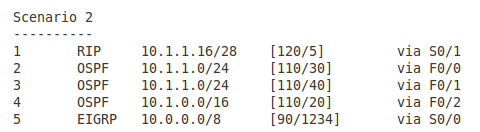
Pic. 7 - Scenario 2.
Pic. 8 - Scenario 3.

Pic. 9 - Scenario 4

Pic. 10 - Scenario 5

The answers to the question (all scenarios)
Scenario 1Entry 2 is the correct answer. The egress interface is F0/0.
The router looks for the longest match in the routing table first. Entry 2 learned from RIP has the longest number of bits that are identical with the destination IP (it is the most specific). The remaining sources (OSPF and EIGRP) have fewer bits that match the destination address (they are less specific). The fact that they are more trusted does not apply here since the longest match is always preferred.
Scenario 2
Entry 1 is the correct answer. The egress interface is S0/1.
Just like in the scenario 1, the router looks for a longest match in the routing table first.
Entries 4 and 5 have 8 bits and 16 bits in common with the destination address respectively. Entries 2 and 3 have 24 bits in common. The longest match is the entry 1 having 28 networking bits that are identical with the IP address 10.1.1.17. You can check it by converting the last byte into the binary notation.
Scenario 3
Entry 2 is the correct answer. The egress interface is F0/0.
We can safely rule out the Entries 1 and 4 due to the length of network mask (not the best matches). We're left with Entries 2 and 3. Both have the same number of bits that are identical bits with the destination address (24). Both prefixes come from the same source (OSPF) and as a result of that have the same Administrative Distance value = 120. The tie breaker is going to be the metric value. Entry 2 has a cost of 30 and entry 4 has cost of 40. The lowest is the preferred one.
Scenario 4
Entry 2 is the correct answer. The egress interface is S0/0.
All five entries have the same length of prefix mask, so after longest match rule check we have five candidates. However, entries 4 and 5 come from OSPF and have higher AD (120) than the first three entries coming from EIGRP routing protocol (90). The lower AD here is preferred. We can rule 4 and 5 out now. Again, all three of them left, have the same AD (90). The tie-breaker is the value of metric again.
Scenario 5
Entries 1 through 3 are the correct answer. The egress interfaces are S0/0, S0/1, and S0/2. The router is going to perform load balancing (traffic sharing).
We can rule out entries 4 and 5 like in the scenario 4. The remaining entries 1 through 3 come from EIGRP (AD=90) and their metrics are the same.


