Showing posts with label authentication. Show all posts

Mar 13, 2013

Lesson 46 - EIGRP Fundamentals Part 4 - Troubleshooting


In this post I'd like to show you how problems in EIGRP can manifest themselves and how to find and fix problems that are less conspicuous. All in the scope of the CCNA level.
Pic. 1 - Topology Diagram.
Icons designed by: Andrzej Szoblik - http://www.newo.pl

Let's assume that this is a new system and your colleague who's not experienced enough tried to set it up but with no success. Some work was done and the task at hand is to connect successfully the branches with headquarter accomplishing full reachability.

The first thing I'm going to do is to learn the topology diagram to know the addresses and encapsulations which connect the branches with the HQ network.

I log in to R1 and here's my first finding. Check it out:

Pic. 2 - EIGRP First Error.
The above output sent to the console indicates that R1 receives hello packets on its local S0/2 interface from the wrong address (not on common subnet). The IP address of the sender is: 172.32.14.4. R1's interface S0/2 is configured as 172.31.14.1. Clearly wrong address is assigned onR4.

I jump over to R2 and correct the address on S0/2 and make sure it is EIGRP enabled by typing in a right 'network' statement.

R4 Configuration:

!
R4(config)#int s0/2
R4(config-if)#ip address 172.31.14.4 255.255.255.0
R4(config-if)#router eigrp 1
R4(config-router)#no network 172.32.0.0
R4(config-router)#network 172.31.0.0
R4(config-router)#
!

I perform a simple check: I want to make sure that R4's interface S0/2 is running EIGRP protocol. Here's the output:

Pic. 3 - R4's EIGRP Interfaces.

To my great surprise, the interface is EIGRP-enabled but there R1 is not listed as the neighbor (peer). The ping shows no problems reaching R1 (172.31.14.1).

In this situation I decide to use a 'debug' tool. Be careful using 'debug' commands as they may severely impact the operation of the router. More information on how to use debug in lesson 37.

I disable a timestamps so the output of the debug is clearer. As soon as the first information is sent to the screen, I disable debug using 'u all' command (in case you are in other mode than privileged '#' the 'do u all' is used. It is the alias for: 'undebug all'. Here's what the debug reports.

Pic. 4 - Debug EIGRP Packets.

The output reveals that the local router (R4) has problems with authentication of EIGRP packets. Opcode =  5 (authentication off or key-chain missing).

The 'show key chain' shows ... zilch! There's no key chain defined on R4. I need to do it. I'm going to do to errors while configuring key chain in order to show you how they show in the 'debug ip eigrp' statement.

Here's my first erroneous configuration:

R4 Configuration: 

!
R4(config)#key chain EIGRP
R4(config-keychain)#key 2
R4(config-keychain-key)#key-string cisco
R4(config-keychain-key)#
R4(config-keychain-key)#int s0/2
R4(config-if)#ip authentication mode eigrp 1 md5
R4(config-if)#ip authentication key-chain eigrp 1 EIGRP
R4(config-if)#
!

You noticed that I used the key 2. Since, the neighbor adjacency has not been built, I reach for the 'debug eigrp packets' again. Here's the output now:

Pic. 5 - Another Debug EIGRP Packets.

In the ton of gibberish I fish out the above message: 'key not defined or not live'. This is the cause of  the 'invalid authentication'

I check R1 and see that it uses key 1 and not key 2. The mismatch in the key number prevents theR1 and R4 from establishing adjacency.

I'll make one more mistake so that you can see another error related to authentication. Look at my key chain authentication on R4:

Pic. 6 - Running Configuration - Key Chain.
At first glance, all seems okay. But is it?

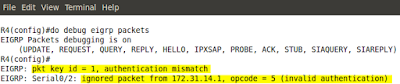
Still R1 and R4 are not neighbors. Let's debug one more time.
Pic. 7 - Debug EIGRP Packets.
This time there is no complaints about key number, but authentication still fails. The problem is with the password used. It does NOT match with the other end. Now, displaying configuration on both R1and R4 shows the password 'cisco'. But is it so? Check the below output on R4:
Pic. 8 - Show Key Chain.
A closer inspection shows that the password cisco is followed by a 'space' character which does not show in the 'show running-config'. This a cause of the problem.

One last error that shows without any debug. Check it out:

Pic. 9 - EIGRP Unsolicited Error Message.
The problem is with the K-values used by R5's neighbor (R2). They do not match on both ends. A quick look at R5 shows that default K-values are used.
Pic. 10 - Show IP Protocols on R5.

The same output on R2 reveals that it all K-values are used to calculate the metric. They do not match on both ends which results in lack of neighbor adjacencies between routers.
Pic. 11 - Show IP Protocols on R2.

A look at EIGRP configuration on R2:
Pic. 12 - EIGRP Configuration on R2.

 A quick fix on R2 and all is good!

R2 Configuration: 

!
R2(config)#router eigrp 1
R2(config-router)#no metric weights
R2(config-router)#
!


Incidentally, EIGRP unsolicited error messages are sent to the screen every few seconds which makes it hard to do the diagnostics. You can temporarily disable logging to the console 0 by typing:

R2(config)#no logging console 

To bring back the defaults:

R2(config)#logging console

In the next post, I'll look at the ACLs (Access Control Lists) and how they can serve different purposes in your network.

Mar 12, 2013

Lesson 42 - OSPF Fundamentals Part 5 - The Lab


I try to keep these posts as short and informative as possible. Since it takes a moment to do this lab and analyze the results, the troubleshooting section is going to be included in the form of a video presentation at the end of this post (available soon).

Here is our topology. I have removed Frame-Relay links as it goes beyond the scope of this tutorial (some really crazy workbook/journal I started a few days ago might give you an idea about this complexity.

But let's get back to business!

Pic. 1 - OSPF Topology Diagram.
Icons designed by: Andrzej Szoblik - http://www.newo.pl

Since there are five different routers and three types of networks (broadcast, point-to-point and loopback) I will create an action plan and implement it step by step. I'll include some stipulations in order to show you a few things which I might have not talked about yet.
Task List

General Requirements:

  • ALL interfaces should be enabled in area 0. 
  • ALL loopback addresses must be advertises with their configured network mask length (/24) or (/28). 
  1. Enable OSPF in the broadcast network connecting R1R2 and R3. Make sure that R1 is elected the DR and R2 is elected the BDR in the broadcast segment (172.31.123.0/24).
  2. Advertise the loopback subnets on R1R2 and R3. On R3 do NOT use the network statement to advertise the subnet of Loopback1. On R3, while enabling OSPF on Loopback2 using the 'network' statement, use the wildcard bits corresponding to the network mask configured (/28).
  3. Enable OSPF between R1 and R4. Advertise the subnet found on R4's loopback0.
  4. Enable OSPF between R2 and R5. On R5 use only one network statement to enable OSPF on ALL interfaces (also the ones created in the future).
  5. Enable the Simple Password authentication in area 0. Use the password 'cisco'.
Lab Solution

Step 1
Enable OSPF in the broadcast network connecting R1R2 and R3.

Note!
Configuration must be done in this order to ensure R1 is elected the DR, R2 is elected the BDR.

R1 Configuration: 

!
R1#conf t
R1(config)#interface f1/0
R1(config)#ip ospf priority 20
R1(config-if)#router ospf 1
R1(config-router)#router-id 1.1.1.1
R1(config-router)#network 172.31.123.1 0.0.0.0 area 0
R1(config-router)#exit  

R2 Configuration:

!
R2#conf t
R2(config)#interface f1/0
R2(config-if)#ip ospf priority 10
R2(config-if)#router ospf 1
R2(config-router)#router-id 2.2.2.2
R2(config-router)#network 172.31.123.2 0.0.0.0 area 0
R2(config-router)#exit

R3 Configuration:

!
R3#conf t
R3(config)#router ospf 1
R3(config-router)#router-id 3.3.3.3
R3(config-router)#network 172.31.123.3 0.0.0.0 area 0
R3(config-router)#exit


Now, let's give the routers a few seconds to go through the finding neighbors, creating adjacencies. Then a quick verification step shows the following:

Pic. 2 - OSPF Adjacencies.
R3 is adjacent with R1 (DR) and R2 (BDR).

Step 2 
Advertise the loopback subnets on R1R2 and R3. On R3 do NOT use the network statement to advertise the subnet of Loopback1. 

Note!
Loopback interfaces are considered the 'stub' networks by OSPF process and advertised with /32 network mask by default. In order to change it, the 'ip ospf network point-to-point' should be used on loopback interfaces.

Note!
After you have enabled OSPF on the loopbacks, you should check before proceeding to the next router's configuration. Use the following command:
Router#show ip ospf int brief 

R1 Configuration:

!
R1(config)#
R1(config)#interface loopback 1
R1(config-if)#ip ospf network point-to-point
R1(config-if)#router ospf 1
R1(config-router)#network 172.31.1.1 0.0.0.0 area 0
R1(config-router)#exit

R2 Configuration:

!
R2(config)#
R2(config)#interface loopback 1
R2(config-if)#ip ospf network point-to-point
R2(config-if)#router ospf 1
R2(config-router)#network 172.31.2.1 0.0.0.0 area 0
R2(config-router)#exit

Note!
The task stipulates that the subnet of Loopback1 must NOT be advertised like others (no network statement). Also, while enabling OSPF on the Loopback2 use the wildcard mask corresponding to the network mask configured there (/28).

R3 Configuration:

!
R3(config)#
R3(config)#interface loopback 2
R3(config-if)#ip ospf network point-to-point
R3(config-if)#interface loopback 1
R3(config-if)#ip ospf network point-to-point
R3(config-if)#ip ospf 1 area 0
R3(config-if)#router ospf 1
R3(config-router)#network 172.31.3.16 0.0.0.15 area 0
R3(config-router)#

Step 3 
Enable OSPF between R1 and R4. Advertise the subnet found on R4's loopback1.

R1 Configuration:

!
R1(config)#
R1(config)#router ospf 1
R1(config-router)#
R1(config-router)#network 172.31.14.1 0.0.0.0 area 0
R1(config-router)#exit

R4 Configuration:

!
R4(config)#interface loopback1
R4(config-if)#ip ospf network point-to-point
R4(config-if)#router ospf 1
R4(config-router)#router-id 4.4.4.4
R4(config-router)#network 172.31.14.4 0.0.0.0 area 0
R4(config-router)#network 192.168.4.1 0.0.0.0 area 0
R4(config-router)#exit

Step 4
Enable OSPF between R2 and R5. On R5 use only one network statement to enable OSPF on ALL interfaces (also the ones created in the future).

R2 Configuration:

!
R2(config)#
R2(config)#router ospf 1
R2(config-router)#network 172.31.25.2 0.0.0.0 area 0
R2(config-router)#exit

R5 Configuration:

!
R5(config)#interface loopback1
R5(config-if)#ip ospf network point-to-point
R5(config-if)#router ospf 1
R5(config-router)#router-id 5.5.5.5
R5(config-router)#network 0.0.0.0 255.255.255.255 area 0
R5(config-router)#exit

Note! 
Of course, before you proceed to the the final step (OSPF authentication) you should check if all neighbors are adjacent and all routers can reach all the addresses in the network.

Step 5 
Enable the Simple Password authentication in area 0. Use the password 'cisco'.

Note!
This configuration is going to break and re-establish OSPF adjacency.

R1 Configuration:

!
R1(config)#
R1(config)#router ospf 1
R1(config-router)#area 0 authentication
R1(config-router)#int f1/0
R1(config-if)#ip ospf authentication-key cisco
R1(config-if)#int s0/2
R1(config-if)#ip ospf authentication-key cisco

R2 Configuration:

R2(config)#
R2(config)#router ospf 1
R2(config-router)#area 0 authentication
R2(config-router)#int f1/0
R2(config-if)#ip ospf authentication-key cisco
R2(config-if)#int s0/2
R2(config-if)#ip ospf authentication-key cisco

R3 Configuration:

R3(config)#
R3(config)#router ospf 1
R3(config-router)#area 0 authentication
R3(config-router)#int f1/0
R3(config-if)#ip ospf authentication-key cisco

R4 Configuration:

R4(config)#
R4(config)#router ospf 1
R4(config-router)#area 0 authentication
R4(config-router)#int s0/2
R4(config-if)#ip ospf authentication-key cisco

R5 Configuration:

R5(config)#
R5(config)#router ospf 1
R5(config-router)#area 0 authentication
R5(config-router)#int s0/2
R5(config-if)#ip ospf authentication-key cisco

After OSPF authentication has been configured you should check if all the adjacencies have been formed and reachability is restored. If you have a problem with this lab in the troubleshooting sections you will find some tips helping you make this lab work.

Troubleshooting

Troubleshooting short videos available soon.

During the weekend your colleague, who's newly hired junior network administrator, was re-configuring your system. He has accidentally erased all backup configurations and also lost the track of all changes that he introduced. You have been called to help him restore the system.

Initial diagnostics the junior administrator has performed revealed the following problems:

Ticket 1
The subnets: 172.31.3.0/28 and 172.31.3.16/28 are no longer reachable from any other router but R3(loopback1 and loopback2 on R3).

Video Presentation:
http://www.youtube.com/watch?v=vKZASyZbDmE

Ticket 2
R4 lost connectivity to all subnets in the network except for directly connected ones.

Video Presentation:
http://www.youtube.com/watch?v=HEOrvxKmQSU

Ticket 3
R5 lost connectivity to all subnets in the network except for directly connected ones.

Video Presentation:
http://www.youtube.com/watch?v=BlS3Z5kV_Rk

Final Verification
Ping using Tcl script - an elegant way of checking connectivity.

Video Presentation:
http://www.youtube.com/watch?v=VuubpKq0rxg

The next post is going to be an introduction to EIGRP routing protocol.

Lesson 41 - OSPF Fundamentals Part 4 - Implementation


In this post, I'm going to present the commands and verification steps with regards to OSPF implementation in a single area. Configuration will also include the authentication of OSPF packets.

If you want to go fancy with OSPF the configuration can be quite challenging. Configuring basic OSPF in a single area is very simple though. There are two basic steps required:

  1. Enable OSPF in the 'config' mode.
  2. Instruct the OSPF process which interfaces should be enabled for OSPF and in which areas the links should operate.
Here is the simple topology we are going to use to see the configuration steps.
Pic. 1 -  Topology Diagram.
Icons designed by: Andrzej Szoblik - http://www.newo.pl

OSPF Basic Configuration
The commands which enables OSPF on an interface can look like the below.

Pic. 2 - Example of OSPF Configuration.
router ospf 1 - This command starts the OSPF process 1 on R1.
network 10.1.0.0 0.0.255.2555 area 0 - This statement enables OSPF process on all interfaces which IP addresses are 10.1.x.x (where x.x can be any number as the last two bytes are not checked by the wildcard mask).

What is the wildcard mask in the above statement?

Wildcard mask is an inversed network mask. The bits in the wildcard mask which are set to '0' will check the corresponding bits in the IP address. The bits in the wildcard mask which are set to '1' will ignore the corresponding bits in the IP address.

Pic. 3 - OSPF Wildcard Mask.
Look at the Pic. 2 again. According to the network statement, OSPF will be enabled on F1/0 and S0/1 of R1 (pic. 1).

What network statement could we use in order to enable OSPF on s0/1 interface but not on F1/0?

I can give you a couple of examples. Remember that wildcard mask will use '0s' to check bits in the address and '1s' will ignore them.

Example 1

R1(config)#router ospf 1
R1(config-router)#network 10.1.13.0 0.0.0.255 area 0

This way the wildcard bits are going to check if there are any interfaces which use IP addresses according to 10.1.13.x (where x is any number). These will be OSPF-enabled.

Example 2

R1(config)#router ospf 1
R1(config-router)#network 10.1.13.1 0.0.0.0 area 0

The second example will enable OSPF on the interface that has the EXACT IP address 10.1.13.1. The wildcard bits consists of all '0s' so ALL the corresponding bits in the IP address used must match in order for the interface to be running OSPF protocol.

As you already know, the moment we enable OSPF on an interface, the routing process begins to send the 'hello' packets trying to discover the neighbor(s). If they are discovered the system begins to check parameters in the OSPF header and hello packet. If they agree on the mandatory fields (hello/dead intervale etc.) the are going through several phases to finally synchronize their LSDBs.

Of course, the network statement with wildcard mask does not influence what network mask is going to be advertised along with the IP address. OSPF, being a classless routing protocol, will advertise their networks/subnets as per configuration on the interfaces.

So, let's configure OSPF as per topology diagram (pic. 1) and observe the process of reaching the FULL state (adjacency) using the debug. I will use the most specific wildard mask here but you already know there are a lot of options available to start OSPF on the interfaces.

R1 Configuration:

R1(config)#router ospf 1
R1(config-router)#network 10.1.1.1 0.0.0.0 area 0
R1(config-router)#network 10.1.13.1 0.0.0.0 area 0
R1(config-router)#network 172.16.101.1 0.0.0.0 area 0
R1(config-router)#

R3 Configuration:

R3(config)#router ospf 1
R3(config-router)#network 10.1.3.3 0.0.0.0 area 0
R3(config-router)#network 10.1.13.3 0.0.0.0 area 0
R3(config-rotuer)#network 172.16.103.3 0.0.0.0 area 0
R3(config-router)#

Now, here's the output of the debug statement on R3. Pay attention to the highlighted words and compare them with the OSPF Neighbor State Machine (lesson 38 in the archive of this blog). 

Pic. 4 - Debug IP OSPF Events on R3.
Notice, that it is a point-to-point network, so there is no election of DR and BDR roles.

As part of practical exercise, try to use the same debug in you lab on routers connected using broadcast (Ethernet) links. Watch for DR/BDR election.

OSPF Verification Commands
It is important to be able to perform some basic verification steps. Here are the commands that you will use most often.

First, let's check if our network statement was correct (OSPF is enabled on the appropriate interfaces).

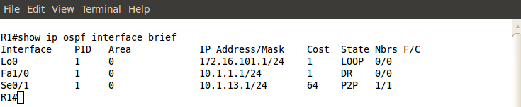
Pic. 5 - OSPF-enabled Interfaces.

You can also see a detailed output which shows more information with regards to OSPF running on an interface. Check it out.
Pic. 6 - OSPF-enabled Interface Detailed Output (Fa1/0).


Then, I want to make sure that R1 is in FULL state with R3. Here's my command:

Pic. 7 - OSPF Neighbor Check.

Two more commands will be useful as well. First one showing the brief output of LSDB (more detailed output is beyond the scope of this tutorial).

Pic. 8 - OSPF Database.

Notice that both R1 and R3 advertise four links. The loopback0, F1/0, and S0/1 which counts as two links (point-to-point interfaces are advertised as two: the IP address of the next hop and the subnet/network IP).

And finally, the content of OSPF routing table:

Pic. 9 - OSPF Routing Table.

OSPF Authentication
As part of implementation we can authenticate OSPF packets to prevent some rouge routers joining our OSPF domain. If someone configures and plugs in the router, it won't become adjacent with others in the domain unless the right method and password are used.

There are two methods to authenticate OSPF packets:

  1. Simple Password - The password is sent in the clear text format.
  2. MD5 - The password is not sent at all. The digest is created using the shared password between neighbors.
Both methods can be implemented using two different ways.

Let's start with Simple Password method.
Method 1 (password must match on both routers; here: S3cr3t)

R1(config)#router ospf 1
R1(config-router)#area 0 authentication
R1(config-router)#exit
R1(config)#interface serial0/1
R1(config-if)#ip ospf authentication-key S3cr3t

Method 2

R1(config)#interface serial0/1
R1(config-if)#ip ospf authentication
R1(config-if)#ip ospf authentication-key S3cr3t
R1(config-if)#

The first command enables OSPF authentication using Simple Password method (area 0 authentication or ip ospf authentication)

The second command specifies the password that is going to be used (ip ospf authentication-key)

In the first method, OSPF authentication is enabled on ALL interfaces configured to operate in area 0. The second method allows more control as to which interfaces will be sending authenticated OSPF packets.

Pic. 10 - Simple Password Authentication Enabled.

MD5 method can also be configured in two ways.
Method 1 (password must match on both routers; here: S3cr3t)
R1(config)#router ospf 1
R1(config-router)#area 0 authentication message-digest
R1(config-router)#exit
R1(config)#interface serial0/1
R1(config-if)#ip ospf message-digest-key 1 md5 S3cr3t

Method 2

R1(config)#interface serial0/1
R1(config-if)#ip ospf authentication message-digest
R1(config-if)#ip ospf message-digest-key 1 md5 S3cr3t
R1(config-if)#

Both the password (here: S3cr3t) and the key number (here: 1) must match between the neighbors.

Use: show ip ospf int s0/1 to check MD5 authentication.

You might try out the following two commands and see what they show: 

R1#show ip protocols
R1#show ip ospf

The next post is going to be the last one in the OSPF series. We are going to configure OSPF in the more complex topology as well as use some troubleshooting techniques to fix the common configuration issues.

Lesson 39 - OSPF Fundamentals Part2 - Hello Packets


Following the previous post, let's continue to look at OSPF basic operation. In this lesson we will focus our attention on the exchange of OSPF Hello packets in order to reach the state allowing LSA exchange.

If these two posts (38 and 39) are a bit too much for you, try to read them again and next week look at my youtube channel. I should have some video published there showing you these things again but this time in on the command line interface.

Before OSPF routers distribute the routing information among their neighbors, they will go through certain stages of operation as explained in Lesson 38. OSPF packets are utilized to take a router from the DOWN state all the way up to the FULL state of operation. We must then, take a closer look at OSPF packets, especially at the Hello packet without which this magic would not be possible.

OSPF uses five types of packets to communicate (explanation of OSPF packet type can be found in my previous post). They are encapsulated in the OSPF header. The whole packet looks like shown in pic. 1.

Pic. 1 - OSPF Packet Encapsulation.
Icons designed by: Andrzej Szoblik - http://www.newo.pl

OSPF header contains the following pieces of information:

Pic. 2 - OSPF Header.
Icons designed by: Andrzej Szoblik - http://www.newo.pl

Version - The OSPF version, currently used version is 2. Version 3 is OSPF for IPv6.

Type - The type of OSPF packet (type 1 through type 5).

  • Type 1 - Hello
  • Type 2 - Database Description
  • Type 3 - Link State Request
  • Type 4 - Link State Update
  • Type 5 - Links State Acknowledgement
Packet Length - The length of the protocol in bytes including the standard OSPF header.
Router ID - The router identifier in OSPF .
Area ID - The 32 bit number representing the area in which the interface operates.
Checksum - The number used to check the integrity of the packet including the header (excluding authentication).
AuType - The type of OSPF packet authentication.
  • 0 - no authentication
  • 1 - simple password (clear text) authentication
  • 2 - MD5 authentication
Authentication - The 64 bit field used for authentication

Hello Packet
In order for OSPF routers to exchange their routing databases, they must first discover themselves using so called Hello protocol and agree on a number of parameters. Hello packet (OSPF Type 1 packet) is used to discover the neighbors and exchange these initial parameters.
The purpose of Hello protocol can be summarized as follows:
  • Hello packets are used to discover OSPF neighbors.
  • Hello packets advertise certain parameters (some of the must match in order to become the router's neighbor).
  • On Broadcast or NBMA networks Hello packets are used to elect DR/BDR roles.
  • Hello packets are used as a keepalive mechanism. If the router does not hear the neighbors' Hello packets in a given time (DeadInterval), it considers it down and invalidates information obtained from it.
  • Hello packets ensure bidirectional communication. The router must see its own RouterID in the 'neighbor' field of the Hello packet it receives.
Before I explain what must match in the Hello packets for the routers to reach so called 2-way state, let's take a look at the Hello packet structure.

Pic. 3 - OSPF Hello Packet.
Icons designed by: Andrzej Szoblik - http://www.newo.pl

Network Mask - The network mask of the originating interface.
Hello Interval - How often Hello packets are going to be sent.
Options - OSPF options. One of them is a 1 bit flag called: E-bit which denotes the type of area in which the interface operates (1=normal, 0=stub).
Router Priority - Used on Broadcast and NBMA networks to elect DR/BDR. The higher the number, the more likely for the router to become DR and the second highest number becomes BDR. After the election has been accomplished, the number is no longer used to influence DR/BDR role (non-preemptive).
Router Dead Interval - The maximum time before a silent router is declared down (no Hello packet from it in this time).
Designated Router - DR is elected in Broadcast and NBMA network. This field in the Hello packet carries the IP address of the DR on the common subnet (only Broadcast and NBMA networks).
Backup Designated Router - BDR is elected in Broadcast and NBMA network. This is the IP address of DR on the common subnet (only Broadcast and NBMA networks).
Neighbor - The router IDs from which valid Hello packet was received in the last DeadInterval time.

2-way State
OSPF-enabled router is a bit picky when it comes to its operation and choosing its neighbors. In order for the OSPF routers to exchange LSAs (information about network reachability), they must reach the 2-way state first which indicates that some mandatory parameters in their Hello packets are identical between them. The OSPF header encapsulates the Hello packet. Below picture shows this encapsulation and the light-red dots indicate the parameters that must match between the neighbors.

Pic. 4 - Hello Packet Encapsulation.
Icons designed by: Andrzej Szoblik - http://www.newo.pl

So, in a nutshell, the following conditions must be met for the two routers to become neighbors:

  1. The routers must be on common subnet (it's true for all IGP routing protocols).
  2. The Hello and DeadInterval timers must be identical between the neighbor candidates.
  3. The area ID, where the OSPF-enabled interfaces of both neighbors operate, must be identical.
  4. The type of area where the two neighbors must be identical (either normal or stub area).
  5. The type and authentication password (if used) must match between neighbors.
Only if the routers agree on the parameters mentioned above (exact match) and their router IDs are listed in the neighbor's Hello packet '(neighbor' field in the Hello packet) can they reach the2-way state and proceed to ExStart, Exchange, Loading and finally Full state. I will show you the process of going through all phases in the next post using 'debug ip ospf adj' command.

After achieving bidirectional communication between the routers (2-way), they will enter the ExStartstate. During this phase the routers are going to elect the Master and Slave roles to perform the database synchronization in an orderly fashion. During the ExStart state they will also check their MTU size. If it does not match, they will not go any further (no LSA exchange is possible). This is generally not a problem between routers, but if you create configuration between a multilayer switch and a router, this might be a problem if the switch uses larger MTU size than 1500 bytes.

Routers typically use MTU=1500 bytes. On a multilayer switch running OSPF you can check it by issuing the following command:

Switch#show system mtu

If MTU is not 1500 bytes, you can disable MTU check on the interfaces in question:

Router(config-if)#ip ospf mtu-ignore

If all is good, they will eventually reach the Full state.

Before I finish this post I must mention that there are two multicast IP addresses reserved for OSPF communication:
224.0.0.5 = All OSPF speaking routers
224.0.0.6 = AllDRouters (DR/BDR listen on this address).

Unfortunately, sometimes these multicast addresses cannot be used on certain types of media (X.25, Frame-Relay, ATM, which are NBMA types of networks). In such situations, by default, unicast transmission must be used to send OSPF packets (the 'neighbor' statement under OSPF process changes mutlicast into unicast transmissions)

Wrapping things up, I need to add that some states require a bit more explanation (for instance, DR/BDR election on Broadcast/NBMA networks), but it will be easier to show it practically in my next post which is going to be about implementation of OSPF on two types of network: Broadcast and Point-to-Point. Running OSPF on these types of network fall under CCNA level of expertise.

Lesson 37 - Routing Information Protocol Part3


In this post, I'm going to finish the RIP fundamentals by showing you RIPv2 in action. After reading this, you will see the major differences presented in the lesson 35 (table1) in practice. Also, I want to present the authentication of RIP packets which protects the RIP domain from being poisoned with false routes.

I'm going to use the same topology diagram as in previous lessons. Currently, the routers are running RIPv1. If you read my previous post, you saw the routing problems we ran into as RIPv1 does not advertise network masks along with IP addresses. The rules for sending and receiving updates are explained in lesson 36.

Pic. 1 - Topology Diagram.
Icons designed by: Andrzej Szoblik - http://www.newo.pl

As you remember, the subnets: 172.31.3.0/28 and 172.31.3.16/28 have not been advertised by RIPv1. There are a few solutions to this problem, but none of them can be resolved using RIPv1. The simplest solution is to use RIPv2 which is classless routing protocol.

Our current RIPv1 configuration looks like this (here: R1 given as and example).

Pic. 2 - R1's RIPv1 configuration

Now, let's enable RIPv2. Below is an example of R1's configuration. The two highlighted commands are now added on all routers in the topology.


R1 configuration:
R1#configure terminal
R1(config)#router rip
R1(config-router)#version 2
R1(config-router)#no auto-summary
R1(config-router)#network 172.31.0.0
R1(config-router)#passive-interface loopback1
R1(config-router)#end
R1#
  • version 2 - Enables RIPv2.
  • no auto-summary - Disables automatic summarization to a class boundary.
Technically, the 'no auto-summary' command is not necessary in this topology, but it will not do any harm. If a router has interfaces configured with IP subnets belonging to different IP classes, this command becomes mandatory if you want to advertise these subnets with their original network masks.

If you display the running configuration of R1, it is going to look like the one below :

Pic. 3 - R1's RIPv2 Configuration.
Now, let's look at the output of 'show ip protocols' on R3. You can compare it with RIPv1 output in the previous post (lesson 36).

Notice, the 'send and receive version'. Only RIPv2 updates will be sent and accepted now. Also, 'Automatic network summarization is not in effect' tells us that 'no auto-summary' command has been used. Also, both loopback interfaces are listed as 'Passive interface(s)'.

Pic. 4 - RIPv2 Information on R3.
It is also a good idea to see RIPv2 advertisements. Again, be careful using 'debug' commands. For better output, I have also disabled the time stamps:

R3 Configuration:

R3#configure terminal
R3(config)#no service timestamps
R3(config)#end


WARNING! 
Extreme care must be taken when using any debug commands on the production equipment. After the diagnostics have been completed, the debug command(s) must be turned off immediately.
All 'debug' commands are VERY dangerous if used on the production routers. They have enormous impact on the CPU and can potentially crash the device. They are typically used as the commands of the last resort during troubleshooting of a given technology when problem cannot be resolved without data they provide. So we tend to use them only in situations when we cannot do any more damage than there has already been done :-).


Pic. 5 - RIPv2 Debug Output on R3.
What are the major differences compared to RIPv1 output in the previous lesson?
  1. Sending and receiving update using version 2.
  2. Received networks/subnets via 0.0.0.0 mean that the advertising router (here: 172.31.123.2) is the best gateway to the given destination.
  3. Sending v2 update uses reserved multicast destination IP address 224.0.0.9 rather than broadcast.
Authentication of RIP Packets
Almost all routing protocols allow to authenticate their packets. This is an extra security mechanism used to protect your routing domain. It is easy to install a routing protocol on a computer and poison the routing domain with illegitimate prefixes. This can disrupt the operation of the whole routing domain.

RIP offers two ways of authenticating their packets:

  1. Simple Password (clear text) authentication.
  2. MD5 based (one-way algorithm) authentication.
Here, I am going to show the more secure one based on well know hashing algorithm called Message Digest 5.

There are three major steps to configure authentication in RIP:

  1. Configure a key chain - It allows to create multiple keys which can be changed automatically if the routers have the time synchronized. The name of the key chain does NOT have to be identical on all routers.
  2. Configure at least one key-string (password) in the key chain - Key number MUST be identical on all routers in the RIP domain. Also, the password (key-string) used for authentication must be identical on all routers.
  3. Apply the key chain - You must apply the key chain on the interfaces where RIP advertisements will be exchanged between the neighbors.

This configuration must be identical on all routers in the RIP domain. Here, I present the configuration on R3.

Step 1
Create a key chain. The name of the key chain (here: RIP).

R3#configure terminal
R3(config)#key chain RIP
R3(config-keychain)#

Step 2
Configure at least one key-string (password) in the key chain (must be identical on all routers). I do not use additional options allowing the key-string to timeout. The password used is valid forever.

R3(config-keychain)#key 1
R3(config-keychain-key)#key-string secret123
R3(config-keychain-key)#exit
R3(config-keychain)#exit
R3(config)#

Step 3
Apply the key chain on the appropriate interface(s). Here the packets must be authenticated between R1 and R2 routers so interface F1/0 will use the key chain.

R3(config)#interface f1/0
R3(config-if)#ip rip authentication mode md5
R3(config-if)#ip rip authentication key-chain RIP
R3(config-if)#end
R3#

If you display information about RIP again, you will notice that authentication of RIP packets has been enabled.

Pic. 6 - RIPv2 Authentication.
If neighbors (R1 and R2) do not sign their packets using the same key number and key-string, R3 is going to reject their advertisements. Both R1 and R2 send their update without authentication. The result is that R3 must ignore them.

Check it out:

Pic. 7 - Invalid Authentication.

Once I have configured identical authentication on all routers, here is the debug output showing thatR1 is sending RIP packets with proper authentication.
Pic. 8 - Authenticated RIPv2 Update from R1.

In the next post, I will start exploration of, arguably, the most commonly used routing protocol OSPF.