Showing posts with label mac. Show all posts

Mar 13, 2013

Lesson 56 - Introduction to IPv6 - Address Structure


After a very short introduction to IPv6 types of addresses and the header presentation, let's dig deeper and find out more about IPv6 addresses.

Hexadecimal Address Notation
I have already mentioned that IPv6 global space begins with 2000::/3. This means that all public IPv6 addresses now use three bits which amount to value 2 in hex.

Look at this notation of global address one more time:

2000::/3
This is a shortcut for:

2001:0000:0000:0000:0000:0000:0000:0000/3

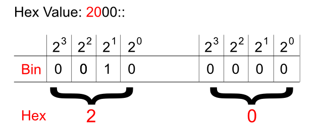
And just like in IPv4 addresses this '/3' tells us to pay attention to the three most significant bits. Hexadecimal to binary conversion is simple. Two digits in hex (for instance: 20) is a one byte value (eight bits). One character stands for four bits (called a nibble). They need to be converted as two separate entities.

Pic. 1 - Hex-to-Binary Conversion.


This way, the hexadecimal 20 becomes 00100000.

In the global IPv6 address scope the first three bits ('/3') will always be set like shown below (as of writing this post):

Pic. 2 - IPv6 Global Address Sequence of Bits.

Okay. What about the hierarchy in IPv6 address?

IPv6 Hierarchy
It is not very different from what we used in IPv4 classes! Do you remember these bits settings in IPv4? If not, look at the below numbers:

Class A - 0xxxxxxx.xxxxxxxx.xxxxxxxx.xxxxxxxx /8
Class B - 10xxxxxx.xxxxxxxx.xxxxxxxx.xxxxxxxx /16
Class C - 110xxxxx.xxxxxxxx.xxxxxxxx.xxxxxxxx /24

The blue color denotes the network portion of the address in these classes. For instance, the '/24' means that 24 most significant bits are the network bits. The remaining ones (eight of them left) are the host bits. This way we create the hierarchy in IPv4 addresses. 


What does it look like in IPv6 then? It is much simpler. See for yourself:

2001:acbd:1234:a1b2:0000:0000:0000:0001/64

The first sixty four bits (blue) are network bits, the remaining ones are the host's interface identifier (host bits). But this, we already know based on the previous post. The network portion is going to be given to us either by the ISP or by the registry (ARIN in the US, RIPE in Europe etc.) if we're a big organization. 

We're told that the length of the prefix assigned to different organizations looks like this:
  • Registries will be assigned /23
  • ISP will be assigned /32
  • Sites will be assigned /48
Say, you are the organization that receives /48 prefix like this:
2001:1234:5678:0000:0000:0000:0000:0000/48.

This gives you two bytes (shown in red) in the network portion to create different networks (red portion: 2^16=65536 different numbers). By the way, get used to the shortcuts:

2001:1234:5678:0000:0000:0000:0000:0000/48 = 2001:1234:5678:0000::/48
IPv6 Interface Identifier (host bits)
How do we get the host portion then? 

In terms of creating the host portion of IPv6 address, if DHCP is not used, we have two options. One way is to do this by hand like presented below (the red color is the interface identifier or the host bits if you will):

2001:1234:5678:1000::1
(abbreviated address which could be expanded to 2001:1234:5678:1000:0000:0000:0000:0001)

But this approach seems somewhat tedious. I mean, who wants to assign addresses on 500 hosts this way?

Another way is to use EUI-64 method which creates the host portion of IPv6 address based on the MAC address of the first Ethernet interface which, at least in theory, should be unique!

Because the MAC address has only 48 bits and not 64, a special procedure has been developed to fill in the gap. Check it out the MAC address of the interface on the router:

Pic. 3 - MAC address of F1/0 Interface.

In the EUI-64 method the operating system takes the MAC address (highlighted) and uses it to create the host bits for the link-local address by default (you can also do this manually). And the same method can be used to assign the host bits in the global address.

Here is the detailed description of how 48 bits of MAC address becomes 64 bit host portion of IPv6 address in EUI-64 method (operating system takes care of these details itself).

Step 1
Flip the 7th bit (counting from left to right) in the MAC address (if it's 1 change it to 0, if it's 0, change it to 1).

In order to do that, operating system must first convert the hexadecimal number of the first byte to the binary form. MAC address used in the example is (as per pic. 3):

CC00.19BA.0010.

(Hex) CC ==> (Bin) 11001100
C=1100

Counting from left to right the 7th bit is: 11001100. This one must be flipped like shown below:
11001110. This gives us the hexadecimal value of: CE.

Step 2
Use the MAC address after modifying the 7th bit in step 1 and inject the FFFE between OUI (first three bytes on the left) and the serial number of the adapter (first three bytes on the right). I will use the colon (:) as the delimiter and blocks of 2-bytes to make it compliant with the IPv6 convention. Look at the result below:

CE00:19FF:FEBA:0010

This way we get 64-bit host portion of the IPv6 address. So my link-local address which uses this method to create the host bits will look like this:

CE00:19FF:FEBA:0010, which is abbreviated to this form:
CE00:19FF:FEBA:10

Step 3
Add the network portion to this construct calculated in step 2. For instance, we know that link-local's network bits are always FF80::/10. So, the whole link-local address is going to be (abbreviated as per Lesson 55's explanation):

FF80::CE00:19FF:FEBA:10
(again, the full 128-bit version is: FF80:0000:0000:0000:E00:19FF:FEBA:0010)

Let's see if this is true when I enable IPv6 support on F1/0 interface. Pay attention to link local address value.

Pic. 4 - IPv6-enabled F1/0 Interface.

Note that just by enabling IPv6 support on the interface IOS automatically creates link-local address using EUI-64, allowing this interface to communicate with hosts residing on this local subnet/network. However, in order to communicate with hosts outside this link-local network, the interface needs a global address as well. This leads us to a correct conclusion that each interface will have two addresses: link-local and global in order to fully operate in IPv6 domain.
IPv6 Global Address Configuration
There are two major methods of configuring IPv6 addresses on our devices:
  • Manual method - You will configure them like we sometimes do with IPv4 right now.
  • Dynamic method - This one offers us IPv6 DHCP servers or the hosts can obtain the network portion of the IPv6 address from their local router (special message is sent called 'Router Solicitation'). In the latter situation the host portion will be generated automatically using the EUI-64 method described above.
Since this post has enough information for one sitting, I'll show you the manual and router solicited methods of configuring IPv6 addresses in my next post. I will also explain what happened to our IPv4 ARP request since broadcast does not exist in IPv6 world anymore!

Mar 12, 2013

Lesson 31 - What is a Router?


We take a lot of things for granted. When it comes to technologies it is not necessarily the best idea. The point is to understand. That is why I am going to start my routing section with fundamentals. Knowing them will allow you to learn more advanced topics on your own later. Make sure you are familiar with my previous posts related to binary numbers and IP addressing before you read this and upcoming ones.

Probably the most appropriate question to start with would be ...

What is a router?
A router is a specialized computer which can connect multiple networks to allow exchange of packets between them. Since a router uses IP header information (layer 3 protocol data unit), to transmit the packets between networks, this ability makes it a layer 3 device. Like switches, routers build a special database which serves as the source of information on what to do with incoming packets. This database is formally called Routing Information Base (RIB). But most often people call it a routing table. How a router constructs a routing table and maintains information in it, will be the topics of quite a few upcoming posts.

A router is in many ways similar to a regular PC. It has RAM and ROM memory chips as well as CPU and motherboard etc. But instead of using hard drive, it uses a flash memory to store files such as the operating system (IOS). Also, what makes it distinct, the operating system and hardware are optimized for fast packet transmissions. Typically the router uses at least two interfaces but more often than not, it has a greater number of them. Cisco operating system is called InternetworkOperating System (IOS). The same name is given to OS used by many Cisco Catalyst switches. Although some of them may also use CatOS.

There is a great variety of interfaces routers can use. For instance, they can connect few Ethernet networks together, but also Ethernet with Wide Area Networks (WANs) such as ATM, Frame-Relay, X.25, ISDN, Broadband etc.

Router Functions
In order for the routers to connect multiple layer 3 networks together, they must be able to do the following:

  • Learn which networks/subnets are available
  • In case there are multiple paths, choose the the best one
  • Keep (routing table) must be up-to-date
  • Translate layer 2 headers (disparate network connections)
  • Keep loop-free paths
  • Make forwarding decisions based on layer 3 headers
Routing is primarily based on hop-by-hop paradigm. This means that if there are multiple routers in the path, a router must find the outbound interface and forward the packet to a next hop router. A router could not care less as to what happens to the packet after it has been expedited.

In order to find the outgoing interface an IP destination address of a packet and a routing table are used. The process whereby destination IP address is the key information to find the outbound interface for a packet is called destination-based routing. However, it is possible to influence that decision making process and choose other criteria such as source of IP transmission, size of the packet, importance of the packet in relation to others or some other parameters rather than destination IP address. When used it is referred to as the traffic engineering. For now though, I am going to focus in on the default behavior.

Before I describe the router's principles of operation, I must make sure we are on the same page with the fundamentals related to the traffic flow.

Let's recall what happens with the packets sent between computers residing in different networks. I will use a simple topology (pic. 1) to review a few facts. Please, get familiar with the picture below first. Pay a special attention to the three headers depicted and numbers in green circles. The numbers refer to the steps below. Of course, this is only a ten thousand foot view of what happens here. Before we jump into the deep water we need to warm up a bit by looking at the process from a high perspective.

Pic. 1 - Traffic Flow and Layer 2/layer 3 Encapsulation/Dencapsulation
Icons designed by: Andrzej Szoblik - http://www.newo.pl

The numbers in green circles mark the important points of the traffic sent from PC1 (left hand side) to the PC2 (on the right side of the picture).

In the explanation presented below I assume that SW1 and SW2 have populated their CAM tables (learned all MAC addresses on the appropriate ports). Here's how it goes.

Step1 
PC1 sends a packet destined to PC2. Since, PC1 has the IP address 192.168.1.1/24, it realizes that the first 24 bits of the destination IP address are different than its own (source: 192.168.1.1, destination: 192.168.3.1). Conclusion: PC2 is NOT in the same layer 3 network, so default gateway (192.168.1.254) must be used to forward the packet to PC2. Knowing it, the IP header is going to use:
  • Src IP = 192.168.1.1
  • Dst IP = 192.168.3.1
  • TTL = 32 (ttl is set by the application, here I use 32 as an example)
IP packet is encapsulation in Ethernet (layer 2) header in order to be put onto the wire. Ethernet header contains source MAC address of the sender, and destination MAC address of R1's F1/0 interface obtained from the computer's arp cache (if not found in the arp cache, arp request is sent):
  • Src MAC: 0000.1111.1111
  • Dst MAC: 0000.2222.2222
Step 2
SW1 receives the frame on its port F0/1. It locates the outbound port (f0/2) for destination 0000.2222.2222. It sends the frame out towards F1/0 port of R1. Neither of layer 2 or layer 3 headers presented in the pic. 1 change during this transmission (parameters depicted).

Step 3
R1 receives frame on F1/0 port. Layer 2 header is inspected by R1. Since the destination MAC address (0000.2222.2222) is the address of F1/0, R1 concludes it is the destination for the frame. Layer 2 header is removed and the content of the message (packet) is processed by the router.R1 processes IP header, reads the destination IP address (192.168.3.1) and compares it with the entries in its routing table trying to find the longest match. More on this in the upcoming post. Once the best path has been found, the routing table points to the outbound interface (F1/1) and the next-hop router's IP address (192.168.2.2) that should be used to expedite the packet.

Step 4
The packet is moved to F1/1 port and the TTL number is decremented by 1 (now TTL=31). Then, the packet is encapsulated in the layer 2 header.The following source and destination MAC addresses are used now:

  • Scr MAC: 0000.3333.3333
  • Dst MAC: 0000.44444.4444
The destination MAC address is obtained from R1's arp cache. If R1 does not know the MAC address for 192.168.2.2 (next-hop router), arp request is sent asking for its MAC address.

Step 5
R2 receives the frame on F1/0 port. It performs the same job R1 has done. It reads the destination MAC address. Since it is the recipient (0000.4444.4444), it dumps the layer 2 frame and processes IP header. It performs layer 3 lookup in its routing table and finds the outbound interface for destination 192.168.3.1. In our example it turns out that the destination network is connected directly to F1/1 interface. In such case, R2 checks arp cache for MAC address of the destination (192.168.3.1) if one is not found, arp request is sent (who's 192.16.8.3.1 ?, I need you MAC address!).

Step 6
The packet is moved to F1/1 interface and before it gets encapsulated, the TTL number is decremented by 1 (TTL=30). The packet is encapsulated in an Ethernet frame header using the following addresses:

  • Src MAC: 0000.5555.55555
  • Dst MAC: 0000.6666.66666
The frame is sent out F1/1 interface.

Step 7
SW2 receives the frame and finds the outbound interface for the MAC address: 0000.6666.6666 int its MAC address table. It is port is F0/2.

Step 8
The frame is sent out F0/2 towards PC2. Fields in the layer 2 and layer 3’s headers remain the same.

The above is just a quick review in case you've forgotten that.

The interesting bit for us now is the router's process of finding the outgoing interface and layer 2 addresses of the next hop device. I'm going to elaborate on this in my next post. Now, let me quickly present the routing table components that are essential in this traffic flow.

Pic. 2 - Routing Table Components.
Components of Routing Table:

  • C and S - point how a router obtained the information (C = connected, S=static route)
  • 192.168.3.0/24 - Example of prefix (destination network/subnet)
  • [1/0] - square brackets show two numbers. First (1) is Administrative Distance, second (0) is Metric
  • via 192.168.2. - the next-hop-router address
How router populates the routing table, what these terms in red mean and how router uses these parameters to pick the longest match and as a result of that the best path, are going to be the main topics of my next post.

Lesson 25 - Switch Port Security


This post is the last one related to layer 2 technologies. With the next posts, I will shift my focus to layer 3 technologies. If you use GNS-3 or dynagen (dynamips emulator), you'll be able to perform all routing tasks on your computer as long as you have IOS image.

Switchport Port Security
This IOS feature (switch only) allows you to limit the number of MAC addresses that will be serviced on a given port. It comes with multiple options such as which MAC address(es) is/are going to be allowed on a given port, and what action should be taken when the violation of the policy occurs. This way, you can further protect your entry point in the network (access switches).

By default, the port security is turned off on all interfaces. In order to turn it on, a port must be in an access mode. Otherwise the command will be rejected. Check out the below attempt of enabling it when the port is in a 'dynamic desirable' rather than an access mode.

Pic. 1 - Port security (switchport port-security) command rejected.

The proper sequence of the commands to enable port security on F0/1 would be as follows:

SW1(config)#interface fastethernet0/1
SW1(config-if)#switchport mode access
SW1(config-if)#switchport port-security

The above configuration applies a default security policy on the port. What settings are going to be used here may vary between switch platforms. But typically, the port in a secure mode allows only aSINGLE MAC address (just one) to be serviced and in the case when the violation occurs, the port will be put in ERR-DISABLE state. This state will put the port down so, no traffic can traverse it.

For the purpose of my presentation, I will use very simple topology (Pic. 2).

Pic. 2 - Topology
Icons designed by: Andrzej Szoblik - http://www.newo.pl

My router R1 is connected to SW1 port F0/1. The MAC address of the R1 (E0/0 port) is:
0050.500f.6600

Now, I want accomplish the two goals:

  • R1 E0/0 port should be connected to SW1 port F0/1. In case, the R1 is connected to any other port on this switch, the communication with the R1 should not be allowed.
  • SW1 port F0/1 should service traffic to/from R1 E0/0 interface. In case, somebody connects more devices to port F0/1 than R1 port E0/0, and/or different device, the port F0/1 should be put in an ERR-DISABLE state.
Let us go ahead and configure it!

I need to show you what the current status of the SW1 port F0/1 is, before we apply port security.

Pic. 3 - SW1 port F0/1 Before Security is applied

As you see, the MAC address of the R1 E0/0 interface has been learned dynamically from the incoming frames on SW1 port F0/1. At this stage, I must explain the difference between dynamic and static entries in the MAC address table.
  • DYNAMIC - the entry is created from the incoming frames by reading the source MAC address field in the Ethernet header. The entry is valid for 5 minutes (300 seconds) by default. If the host with this source address (here R1) does not send any frame towards the port of the SW1 for 300 seconds, the entry is removed. Every time, the R1 sends a frame towards the SW1 F0/1, the entry timer is reset, or if the entry has already been removed, the same MAC address is mapped to the port again.
  • STATIC - the entry (MAC address) is permanently mapped to a specific port. It does not age like a 'dynamic' entry. The switch does not create this MAC address to port mapping by reading the source MAC address, but it is the administrator of the switch that creates it in the global config mode using 'mac address-table static' command.
 So, the question is: what is the difference in operation if you use static over dynamic method?
In case of static mapping of MAC address to a port, you CANNOT move this device to any other port as it will not work! The switch expects to receive the frames sourced from the device on the specific port. If it receives the frames with the MAC address on different port than assigned statically, it will drop the frames from that device.

If you rely on dynamic address learning (default), you can plug in a device to any port and quickly the switch flushes the entry from the old port (where the device was connected previously) and re-learns the MAC address on the new port you have just connected your device to.

Knowing that, we can proceed with our security plan now. I have applied the port access and port security commands like presented above. Now, take a look at the default settings applied on this specific switch platform I use (Catalyst 2950). Bear in mind, that your switch may have different default settings.

Pic. 4 - Port in Secure Mode.

Quick dissection of the output's essential information:
  • Secure Port - F0/1 is now working in a secure mode.
  • MaxSecureAddr - The maximum number of addresses allowed on this port is 1 MAC address.
  • CurrentAddr - At this moment, this maximum limit has been reached.
  • SecurityViolation - Currently there's been no security violation reported.
  • Security Action - In case there is a security violation detected, the port will go DOWN (err-disable).
Let's see which MAC address is now in the secure mode (it should be R1 E0/0).
Pic. 5 - Current Secure MAC Address.

Everything seems good so far. F0/1 port learned dynamically the MAC address of our R1, and is now considered a secured MAC address. One of our two goal plan seems to be working. What if we moved the R1 to another port? What would happen then?

Pic. 6 - MAC address with security enabled.

This specific switch (C2950) has also made the entry 'static' which means, that if you move R1 E0/0 port to another port of this switch, the traffic from R1 will be discarded!

Well, you can further improve the security of your R1. The problem is, that with current configuration, you can reboot the switch and while doing so, you can plug in a different device to F0/1. This way the newly learned MAC address upon reload of the switch becomes the secure one. 

In order to make it more secure, it is recommended that you configure the secure MAC address permanently. Just like in the example below:

SW1(config)#interface f0/1
SW1(config-if)#shutdown
SW1(config-if)#switchport port-security address 0050.500f.6600
SW1(config-if)#no shutdown
SW1(config)#end
SW1(config)#wr

Pay attention to some of the commands presented. I shut the port down first to flush the current (the same) MAC address. Otherwise this command would be rejected (duplicate MAC address). Then, after adding the MAC address, I brought the port up and saved my configuration.

Now, the MAC address becomes the part of configuration and the security applied can withstand the reboot of the switch.

Pic. 7 - Configuration saved in NVRAM.

There is one more command that offers more detailed output (pic. 8).

Pic. 8 - Port security detailed output

Take a look at some interesting options shown below:

Pic. 9 - Port security options.

  • Aging - there are two types of secure MAC address aging: 'absolute' and 'inactivity'. The former, allows to specify how long the MAC address should be considered secure, the latter decides that MAC address is no longer secure if it is not transmitting data in a given time. Both parameters can be configured but, as per default, the secure MAC addresses do not age.
  • Mac-address - like in my configuration, this option specifies which address is to be secured. You can type in a specific MAC address (like I did) or use a 'sticky' keyword. When 'sticky' is used the MAC address(es) already learned on the port become part of the interface's configuration. However, adding MAC address manually is recommended. Just like I did.
  • Maximum - how many MAC addresses can be considered secure on a given port (platform dependent). The default is: 1.
  • Violation - this option allows to choose one of the three options as to what action must be taken if the violation of the security is detected. 
Port Violation Actions
  1. Protect - when the port receives the traffic from the MAC addresses which are not configured as secure, it silently drops those transmissions. There is NO notification logged about the violation occurring on a port.
  2. Restrict - similar to 'protect' only the switch logs the violations detected.
  3. Shutdown (default) - the port will transition to err-disable upon detecting the violation.
Let me quickly show you what happens if my switch detects the violation of the port security.

I am going to change the MAC address on my E0/0 port of R1 to:
0000.aaaa.aaaa

As a result of that, the first frame sent towards the SW1 F0/1 will cause the violation of my policy (wrong MAC address, and the port allows only one MAC address previously assigned as the secure one).

Pic. 10 - The log generated after violation on the port occurred.

Below is the status of the port now.
Pic. 11 - Port in err-disable state upon violation of security.

The only way to rectify the situation is to do the following:
  1. Plug in the device with the right (secure) MAC address back to the port F0/1.
  2. Shut the port down manually (administrative mode shutdown).
  3. Bring the port up using: 'no shutdown' command.
This way has one major disadvantage. Well, it seems you have to perform the three steps mentioned above which looks like you are being punished for somebody else's security violation.

You can configure two additional commands in the global configuration mode which allow your switch to attempt to bring the port automatically after a period of time in err-disable mode. If the proper device is already connected, the port will be fully functional again.

SW1(config)#errdisable recovery cause psecure-violation
SW1(config)#errdisable recovery interval 60

The first command instructs the switch to pay attention to any ports in err-disable state. If such ports exist, the switch will attempt to bring them up after 60 seconds of putting the in err-disable mode (second command).

In my next post, we will start talking about layer 3. I propose that we refresh our knowledge of binary system which is essential to understand IP addressing scheme.

Lesson 22 - Spanning-Tree Cisco Enhancements


My previous two posts hopefully shed some light on IEEE 802.1d protocol (yes, it is STP). There are two more things I would like to add to that picture. The first thing, deals with situations when the topology changes and how it affects the STP time of convergence. The convergence here, means the time it takes to recompute the STP tree in order to keep the loop free paths upon failure. The second thing, I'd like to bring up is the Cisco STP enhanced the STP operation to decrease the time of convergence compared to the industry standard STP.

Before we delve into the details though, I need to explain something about BPDU frames first. It is true that it is the root bridge that originates those frames and sends them out its designated ports ( downstream, every 2 seconds by default). It is also true, that all other switches (non-root bridges), propagate them downstream out of their designated ports. This way all switches receive the information as to which switch is the root bridge in the network and if it is still functional.

However, what I withheld in previous posts was the types of BPDU frames. There are three types of those:

  • Configuration - the type of BPDU which the root bridge sends every 2 seconds, and other switches propagate those out of their Designated Ports (downstream).
  • Topology Change Notification (TCN) - the type of BPDU that a switch will send if it detects the topology change (port going down, or TCN received). This BPDU is sent out the Root Port (upstream) towards the root bridge informing it, that the tree needs to be recomputed.
  • Topology Change Acknowledgement (TCA) - the type of BPDU that is sent back to the sender of TCN BPDU, acknowledging the reception of the notification.

How do those BPDUs fit into the grand scheme of things?

The default timer of how long the entries are kept in the MAC address table is 300 seconds (5 minutes). This means, that if a host connected to a port of the switch does not speak for at least five minutes, its MAC address is removed from the CAM table. That is a way too long for the switch to re-learn computer's MAC addresses if the STP topology changes.

But why do those MAC entries have to change?

Please, consider the Pic. 1 below. By now, you should be able to tell which ports of the switches are going to learn the PC1 and PC2 MAC addresses. Go ahead, click the Pic. 1, and put down on a piece of paper the switch names and the ports that learn MAC addresses of the PC1 and PC2. That is going to be a good refresher of how switches learn MAC addresses dynamically.

Pic 1 - STP Topology.

Icons designed by: Andrzej Szoblik - http://www.newo.pl
If your answers match mine below, that means that you have mastered the lessons on bridging/switching and STP.

SW1 CAM:
F0/1 - 0000.1111.1111
F0/2 - 0000.2222.2222

SW2 CAM:
F0/1 - 0000.2222.2222
F0/2 - no mac addresses learned since the port is NDP
F0/3 - 0000.1111.1111

SW3 CAM:
F0/1 - 0000.1111.1111
F0/2 - no mac addresses learned as PC1 communicates using SW1
F0/3 - 0000.2222.2222

SW4 CAM: 
F0/1 - no mac addresses learned as SW2's port F0/2 is NDP
F0/2 - 0000.1111.1111
F0/2 - 0000.2222.2222

Now, lets create a problem that causes the topology change in our network. Consider Pic. 2 which shows us why some ports must re-learn the MAC addresses of PC1 and PC2.

Pic. 2 - STP Network Problem
Icons designed by: Andrzej Szoblik - http://www.newo.pl

Given the situation, STP needs to recalculate topology since we lose active connections betweenSW1 and SW2. If it were not for the STP operation in such circumstances, it would take 5 minutes (300 seconds) for the switches to re-learn MAC addresses according to the situation presented in Pic. 3. The resulting topology diagram is depicted below.

Try to put down on the paper which MAC addresses should be learned on which ports of the respective switches after failure (Pic. 3).

Pic. 3 - Topology after losing the connection between SW1 and SW2.
Icons designed by: Andrzej Szoblik - http://www.newo.pl

SW1 CAM: 
F0/1 - down 
F0/2 - 0000.1111.1111
F0/2 - 0000.2222.2222

SW2 CAM: 
F0/1 - down 
F0/2 - 0000.2222.2222
F0/3 - 0000.1111.1111

SW3 CAM: 
F0/1 - no MAC addresses learned
F0/2 - 0000.1111.1111
F0/3 - 0000.2222.2222

SW4 CAM: 
F0/1 - 0000.1111.1111
F0/2 - 0000.2222.2222

In order to decrease the time of re-learning MAC addresses, upon failure SW1 is going to send TCN BPDU out its Root Port. Normally, the Configuration BPDU are sent out Designated Ports NOT the Root Port. But this failure prompts the switches to notify the root bridge about the topology change. That is why, they will send TCN BPDU out their Root Port. All switches, in the path of this TCN BPDU must send the TCA BPDU (acknowledgement) back to the sender and forward TCN BPDUtowards the root bridge. As soon as the root bridge has been notified about the topology change, it begins to send TCN BPDUs out its Designated Ports, so other switches in the network also get notified to give them a chance to flush MAC addresses, recompute the tree and re-learn the MAC addresses according to the new topology (Pic. 3). This reduces the time of convergence from 5 minutes to about 30 - 50 seconds time, depending on the nature of the change.

You might question that and say that the default timers used here (30-50 second delay) are still inappropriate for today's networks transmitting voice, video and data. And you are quite right saying so. The mechanism is still not good enough. But remember, that those timers were designed as SAFE values (not causing the loops) given the maximum diameter of network of seven switches (hops) between the root bridge and the bottom switches. Also, remember that STP was designed when there were no multimedia transmissions being sent across the switches. Is there a solution to those timers? Of course. You may change them manually but DO NOT DO THAT unless you are very experienced with STP operation. Another option is to use some proprietary features implemented in Cisco switches.

Cisco with their STP Enhancement are able to decrease this 30-50 second timers even further allowing video, voice and data co-exist in our layer 2 networks. Keep in mind, that these enhancement are Cisco proprietary STP add-ons: 
  1. STP Portfast (now part of standard implementation as well).
  2. STP Uplinkfast.
  3. STP Backbonefast (this one is beyond the scope of this tutorial).
Let us see how the first two can change the behavior of our sample topology.

STP Portfast feature should be configured on all EDGE ports, i.e. the ones that connect devices that do not send BPDU frames and cannot create loops. These would be your computers, servers, printers etc. What STP Portfast does, it simply skips the LISTEN and LEARN states, going directly to FORWARD state if there was TCN announced or the port in question is just brought up. Think about it. It makes no sense to flush the MAC addresses on the ports that connect the computers directly, since the topology change is not going to affect them. In the topology presented in this tutorial (Pic. 1, 2, and 3), the topology change did not affect the ports F0/3 on both SW2 andSW3 where PC1 and PC2 are connected respectively. They are still connected where they were before the topology change and their addresses are mapped to the same ports as before the change. So, there is no point of flushing the MAC address table entries on SW2 port F0/3 and SW3port F0/3. These ports are the candidates for STP Portfast. Because STP Portfast-enabled ports go FORWARD almost immediately, it is highly recommended to use this feature on ports connected to computers in order to avoid problems of getting the IP address using DHCP services.

There are two ways of enabling STP Portfast feature.

Method 1
In the global configuration mode, type in this command:

SW1(config)#spanning-tree portfast default

All ports that are discovered as EDGE ports (more on that in my next post about Rapid STP), will have STP portfast enabled by default. You can check that using a detailed STP output regarding a port (here F0/1):

SW1#show spanning-tree interface f0/1 detail 

The output shows that STP  portfast has been enabled on this port (look at BPDU received = 0, candidate for portfast):

Pic. 4 - STP F0/1 Detailed Output.

Method 2 
Another method is to type in the following command directly on the chosen port:

SW1(config)#interface f0/1

SW1(config-if)#spanning-tree portfast

This way, we turn on STP Portfast unconditionally (whether port does or does not receive BPDUs).

The second STP enhancement is STP Uplinkfast. This one should be configured on all ACCESS switches (the leaf switches in our topology NOT distribution ones). The feature that is enabled in the global config mode, shortens the time it takes to transition NDP port into RP role upon losing the current Root Port.

In our topology, consider SW2 that has lost its Root Port (F0/1, Pic. 2). Normally, that is without STP Uplinkfast enabled, it would take 30 seconds for the F0/2 port to transition to an RP role. Keep in mind that F0/2 does not have go to blocking state since it keeps receiving superior BPDUs with the Root Bridge ID. Thus, only 30 seconds are required by default (LISTEN+LEARN states). With STP Uplinkfast enabled, Cisco guarantee that the transition of F0/2 to forwarding state (RP role) is going to happen in under 5 seconds.
The configuration of STP Uplinkfast is done in the global config mode as shown below:

SW1(config)#spanning-tree uplinkfast

Similar, in functionality, is STP Backbonefast that could be implemented on distribution switches. However, the details of this feature are beyond the scope of this tutorial.

In my next post, I'm going to briefly present Rapid Spanning-Tree Protocol (IEEE 802.1w) and how it differs from a regular STP (IEEE 802.1d).

Mar 11, 2013

Lesson 19 - Spanning-Tree Protocol Overview


Vlans described in the previous posts are very important elements of building modern networks. Equally important piece of technology is IEEE 802.1D, commonly known as Spanning-Tree Protocol. In the following few posts, I will focus on its application and basic operation.

If your network consists of layer 2 switches that allow computers connect and exchange data, you will need to consider the design that can withstand some types of failure.


Redundant Connections 

Consider the following layer 2 design. Imagine that the SW1SW2 and SW3 switches connect many devices and there is only a single connection between the switches like depicted in the Pic1.

Pic. 1 - Switch Topology Without Redundancy
Icons designed by: Andrzej Szoblik - http://www.newo.pl

Should either of the links between the switches break, the communication between many devices fail. Such design creates a single point of failure. We could easily tweak this simple design to make it more resilient by adding an extra path between SW2 and SW3. The below picture shows this modified design.
Pic. 2 - Redundant Paths
Icons designed by: Andrzej Szoblik - http://www.newo.pl

Unfortunately, creating the extra path here comes at a cost. The redundant connection (Pic. 2) between SW2 and SW3 creates a loop. The loop in turn, will create three serious problems. The last one in the list will eventually render our system unavailable. Let's see what these problems are.

Duplicate Frame Delivery

Pic. 3 - Problem 1 - Duplicate Frame Delivery
Icons designed by: Andrzej Szoblik - http://www.newo.pl 

Look at the pic. 3 and imagine SW2 and SW3 do not have the MAC address of PC3(0000.3333.3333) in their databases (CAM). This can happen if the PC3 doesn't speak for more than five minutes. This is the default time MAC address is kept in the database without refreshing it. Then, we have PC1 sending frame towards PC3. As you recall, SW2 will flood the frame out of its active ports if it does not know where PC3 is located (unknown destination MAC address). The frame travels out SW2's port F0/13 towards SW1 and out the port F0/12 towards SW3SW2 will deliver the frame to PC3. Since SW3 floods the frame out as well, it will be sent towards SW1 out of its port F0/14. Then, SW1 obediently delivers the same copy of the frame to PC3 again.


MAC Address Table Instability
Another issue caused by the loop we have created will make switches change the MAC addresses depending on where they hear the sender. Consider pic. 4 below.

Pic. 4 - Problem 2 - MAC address table instability
Icons designed by: Andrzej Szoblik - http://www.newo.pl

Again, let us assume that none of the switches in the picture knows where PC3 is connected. This means they have not learned its MAC address yet. In our scenario, PC1 sends the frame to PC3(destination MAC: 0000.3333.3333). SW2 floods the frame out F0/12 and F0/13 ports.

Now, SW3 receives this frame sourced with 0000.1111.1111 MAC address (PC1). It learns the source MAC address and maps it to its F0/12 port where it arrived. Since SW1 does not know wherePC3 is connected (at least right now) it will flood this frame out all active ports. This way, the frame is sent out SW1's port F0/14 towards SW3SW3, upon receiving the frame on its F0/14 port, reads the source MAC address (0000.1111.1111) and maps it to port F0/14 this time. This causes a little confusion as SW3 learned it earlier on and it was port F0/12 before. Previous mapping is removed and F0/14 becomes the outbound port for 0000.1111.1111 now.

Broadcast Storm
The last problem is really severe. It can bring our traffic to a halt. Take a look at pic. 5 below.

Pic. 5 - Problem 3 - Broadcast Storm
Icons designed by: Andrzej Szoblik - http://www.newo.pl
In this scenario, PC1 sends a broadcast frame. SW2 upon receiving it, floods it out all its active ports. SW1 receives it on port F0/13 and floods it out of other ports. SW3 receives the broadcast frame on its F0/12 port and floods it. Then, a tad later it receives this same broadcast frame from SW1 and again it floods it out all active ports except the port it arrived on. You can write the rest of the story on your own. This broadcast is running in the loop in both directions endlessly. Well, not exactly endlessly. It is true that there is not mechanism to stop it, but all three switches in the topology will be so busy sending out this broadcast, that eventually all its resources are consumed and they stop sending anything at all. If you look at switches that experience a broadcast storm, you will notice that all their LEDs are flashing amber like a Christmas tree. In a few seconds the switches become unresponsive. An attempt to access them remotely using SSH/telnet will fail. Even console connection may refuse to accept your commands. The only way to bring the switches back to the operation is to break the loop by pulling one of those cables.

So, what can we not have redundancy in our layer 2 topology? Of course, we can.

We will run Spanning-Tree Protocol (turned on by default), which will dynamically block redundant connections creating a loop free topology. Should the primary link fail, the one that is in the blocking state will start forwarding the traffic in about 30 seconds by default. Of course, we will need something much faster than 30 seconds, but I will show you that as soon as we know how STP works.

Here I am going to give you just an overview of its operation. But the devil is in the details which we will scrutinize in my next post.

Spanning-Tree Protocol Overview
STP is a layer 2 loop prevention mechanism. Switches running this protocol use special frames called Bridge Protocol Data Unit (BPDU). These frames contain enough information to allow the switches to create a loop free topology. This magic is accomplished using three distinct phases:

  1. Elect a single switch to be the root bridge machine which is the central device in the layer 2 network. This machine will have all its ports in the forwarding state (designated port role).
  2. All other switches (non-root switches), will select a single path towards the root bridge. That port is called the 'root port' and will be forwarding traffic that is destined out of the switch through the root bridge. This path is the least cost (best) path towards the root.
  3. All other switches will select a single path per segment in order to block stop the loop. The port that is forwarding traffic is called designated port. The port that is blocking traffic to stop the loop is called non-designated port.
I will explain all the terms and the above process in details in my next post. Meanwhile, check the pic. 6 first.
Pic. 6 - Spanning-Tree Protocol
Icons designed by: Andrzej Szoblik - http://www.newo.pl

In the above picture, SW1 has been elected as the root bridge. SW2 uses port F0/13 as its root port (the best, or the least cost path towards the root). SW3 uses it port F0/14 as the root port. SW3blocks the port F0/12 to stop the loop. SW2 keeps sending BPDU frames originated by the root bridge (SW1) out its F0/12 port towards SW3.

Now, what is really fascinating that the loop free structure like the above is done automatically (although you want and will affect how it works), and the fact that if the communication betweenSW2 and SW1, or SW3 and SW1 is broken, the SW3 port F0/12 will be put in the forwarding state.

If you are interested in the details how STP works please read my next post (lesson 20).