Showing posts with label configuration. Show all posts

Mar 13, 2013

Lesson 58 - Introduction to IPv6 - Migration


Now, being equipped with some fundamental IPv6 knowledge, we can try to configure RIPng protocol (RIP Next Generation), as well as try to connect two different IPv6 networks over IPv4 cloud. I'm going to use the same topology in the previous lesson.
Pic. 1 - IPv6-IPv4 Topology Diagram.
Icons designed by: Andrzej Szoblik - http://www.newo.pl

Let's start off with enabling RIPng between R1 and R3 followed by some verification steps. RIPng is very similar to RIPv2 we used before. It uses similar mechanism such as split-horizon, maximum hop-count (16 hops), advertisements every 30 seconds, etc. It uses UDP port 521 (RIP uses UDP port 520).

  
Step 1
Configure IPv6 and IPv4 addresses and enable the interfaces. Check point-to-point reachability.

R1 Configuration:

!
interface Loopback0
 no ip address
 ipv6 address 2001:1:1:1::1/64
!
interface FastEthernet1/0
 no ip address
 duplex auto
 speed auto
 ipv6 address 2001:13:13:13::1/64
!
interface Serial0/0
 ip address 10.1.1.1 255.255.255.252
!

R2 Configuration:

!
interface Loopback0
 no ip address
 ipv6 address 2001:2:2:2::2/64
!
interface FastEthernet1/0
 no ip address
 duplex auto
 speed auto
 ipv6 address 2001:24:24:24::2/64
!
interface Serial0/0
 ip address 10.1.1.2 255.255.255.252
!

R3 Configuration:

!
interface Loopback0
 no ip address
 ipv6 address 2001:3:3:3::3/64
!
interface FastEthernet1/0
 no ip address
 duplex auto
 speed auto
 ipv6 address 2001:13:13:13::3/64
!

R4 Configuration:

!
interface Loopback0
 no ip address
 ipv6 address 2001:4:4:4::4/64
!
interface FastEthernet1/0
 no ip address
 duplex auto
 speed auto
 ipv6 address 2001:24:24:24::4/64
!

Verification:

Pic. 2 - IPv6 Ping Test on R1.

Pic. 2 - IPv6 Ping Test on R2.

Since, pinging by IPv6 address is a bit awkward, you can create name-to-ip mapping using the following commands (here: R1 as an example):

R1 Configuration:

!
R1(config)#ipv6 host R3 2001:13:13:13::3
R1(config)#end
!

Then, you can 'ping R3' (name is case insensitive) instead of using its address.

The routing table of R1 looks like this. You should recognize the addresses easily based on the previous post.

Pic. 4 - R1's IPv6 Routing Table.

Step 2
Enable RIPng to advertise loopbacks. Check the reachability.

In order to support IPv6 routing, you must enable support for it using:
'ipv6 unicast-routing'. Starting RIP process will require to configure a tag for the process (can be number or name). Then, you enable RIPng on the interfaces in question (note: there is no network statement to do that).

R1 Configuration:

!
ipv6 unicast-routing
!
ipv6 router rip TEST
!
interface Loopback0
 no ip address
 ipv6 address 2001:1:1:1::1/64
 ipv6 rip TEST enable
!

interface FastEthernet1/0
 no ip address
 duplex auto
 speed auto
 ipv6 address 2001:13:13:13::1/64
 ipv6 rip TEST enable
!

R2 Configuration:

!
ipv6 unicast-routing
!
ipv6 router rip TEST
!
interface Loopback0
 no ip address
 ipv6 address 2001:2:2:2::2/64
 ipv6 rip TEST enable
!
interface FastEthernet1/0
 no ip address
 duplex auto
 speed auto
 ipv6 address 2001:24:24:24::2/64
 ipv6 rip TEST enable
!

R3 Configuration:

!
ipv6 unicast-routing
!
ipv6 router rip TEST
!
interface Loopback0
 no ip address
 ipv6 address 2001:3:3:3::3/64
 ipv6 rip TEST enable
!
interface FastEthernet1/0
 no ip address
 duplex auto
 speed auto
 ipv6 address 2001:13:13:13::3/64
 ipv6 rip TEST enable
!

R4 Configuration:

!
ipv6 unicast-routing
!
ipv6 router rip TEST
!
interface Loopback0
 no ip address
 ipv6 address 2001:4:4:4::4/64
 ipv6 rip TEST enable
!
interface FastEthernet1/0
 no ip address
 duplex auto
 speed auto
 ipv6 address 2001:24:24:24::4/64
 ipv6 rip TEST enable
!

Verification (here just on R1):

Pic. 5 - R1's RIPng Routing Table.

Note!
R3's Loopback has been advertised to R1. The next-hop-address is the R3's link-local address, NOT the globally unique IPv6 address.

Pic. 6 - Debugging RIPng.

Take time and effort in analyzing the output of the debug. Pay attention to the UDP port number used. It is 521 (RIPv1 and RIPv2 use 520). Also notice that the source IPv6 is the router's link-local address and not globally unique one. Also, the destination address is IPv6 multicast address reserved for RIPng: FF02::9.
Another, worth noting fact is that R3 advertises its loopback (2001:3:3:3::/64) and its locally connected network (2001:13:13:13::/64). 

One more command to check RIPng configuration.

Pic. 7 - IPv6 Protocols.

Step 3
Create tunnel between two IPv6 networks over IPv4 island.

Since CCNA official course does not teach how to create tunnels, I will use 6to4 tunneling method which encapsulates IPv6 packet in IPv4 headers to send them across IPv4 network. These posts do not aspire to help you pass the exam. They are designed as an extra, practical help to master the technologies at the CCNA level instead.

R1 Configuration:

!
interface Tunnel0
 no ip address
 ipv6 address 2001:12:12:12::1/64
 ipv6 rip TEST enable
 tunnel source 10.1.1.1
 tunnel destination 10.1.1.2
 tunnel mode ipv6ip
!

R2 Configuration:

!
interface Tunnel0
 no ip address
 ipv6 address 2001:12:12:12::2/64
 ipv6 rip TEST enable
 tunnel source 10.1.1.2
 tunnel destination 10.1.1.1
 tunnel mode ipv6ip
!

Verification:

Pic. 8 - R3's IPv6 Routing Table.

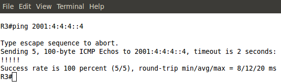
Pic. 9 - Ping Test from R3 to R4.
The Cisco documentation on how to implement IPv6 is available at:
http://www.cisco.com/en/US/docs/ios/ipv6/configuration/guide/12_4/ipv6_12_4_book.html 

If you want to learn more on tunneling methods used during the migration look at:
http://www.cisco.com/en/US/docs/ios/ipv6/configuration/guide/ip6-tunnel.html

Another method called NAT-PT (NAT Protocol Translation) can is explained at:
http://www.cisco.com/en/US/docs/ios/ipv6/configuration/guide/ip6-nat_trnsln_ps6350_TSD_Products_Configuration_Guide_Chapter.html

In my next post, I will address the basics of WAN technologies including some legacy technologies such as Frame-Relay since they are still part of the exam game.

Lesson 54 - Network Address Translation Part 4


It's time to put our theory into practice. We're going to use a single topology and try out different scenarios. They are not related to one another but my intention is to show you the variety of different methods in use. Keep in mind that they are just the few fundamental types of translations but there are more options available and they can become a bit more complex than the ones presented here.

Pic. 1 - Network Topology.
Icons designed by: Andrzej Szoblik - http://www.newo.pl

R2 is playing a role of ISP's router. For the purpose of this presentation I'm not going to use real IP public addresses. I'm going to use 172.x.x.x range and pretend they are public ones.

Addresses used in this lesson are going to be as follows:
Private (LAN) IP = 192.168.1.0/24 and 192.168.2.0/24
Public (Internet) IP = 172.16.1.0/30 (connection to ISP)
Public (Internet) IP = 172.30.1.1 (Internet host used to check NAT)

All these addresses are simulated using Loopback interfaces.

R1 Initial Configuration:

!
interface Loopback1
 ip address 192.168.1.1 255.255.255.0
!
interface Loopback2
 ip address 192.168.2.1 255.255.255.0
!
interface FastEthernet1/0
 ip address 172.16.1.1 255.255.255.252
!
ip http server
!
ip route 0.0.0.0 0.0.0.0 172.16.1.2
!

R2 Initial Configuration:

!
interface Loopback0
 ip address 172.30.1.1 255.255.255.0
!
interface FastEthernet1/0
 ip address 172.16.1.2 255.255.255.252
!
ip http server
!
ip route 172.20.1.0 255.255.255.252 172.16.1.1
!


Scenario 1 - Static NAT
In this scenario I'm going to configure a static (one-to-one) NAT. This type of configuration allows me to present my public services to the Internet clients. Let's pretend that our 192.168.1.1 address is a Web server and is connected to R1 (loopback1 simulates this server). Our ISP gave us two public IP addresses (we pretend they are public anyway).

Inside Global Address Pool:

  • 172.20.1.1/30
  • 172.20.1.2/30

Our web server (192.168.1.1) will be seen on the Internet as 172.20.1.1. Below is the configuration to accomplish that.

R1 NAT Configuration:

!
interface Loopback1
 ip address 192.168.1.1 255.255.255.0
 ip nat inside
!
interface FastEthernet1/0
 ip address 172.16.1.1 255.255.255.252
 ip nat outside
!
ip nat inside source static 192.168.1.1 172.20.1.1
!

Note!
When you assign inside or outside role on the interface, the router is going to add 'ip virtual-reassembly' (dependant on the IOS version you use). At the CCNA level you can ignore the meaning of this command.

Verification:

Pic. 2 - NAT Table.

Note!
Static entry is created allowing transmission towards 192.168.1.1 which is seen as 172.20.1.1 on the Internet. Since we have not specified any layer 4 protocols (tcp/udp) and their ports, all ports are open in R1 allowing access to all ports on the web server. If you wanted to open only TCP port 80, you could use this command instead (more likely in real life scenarios):

!
ip nat inside source static tcp 192.168.1.1 80 172.20.1.1 80
!

Pic. 3 - Accessing Web Service.

Connection succeeds!

Scenario 2 - Dynamic NAT using IP Address Pool.
In this scenario we have the same pool of pretend-to-be-public IP addresses from scenario 1. This scenario will dynamically pick the first available IP address and use it for the host that wishes to send packets to the Internet. Since we only have two public IP addresses, only two hosts can send traffic at the time. Adding the 'overload' keyword will include the port translation and more hosts can reuse these two public addresses (172.20.1.1-2/30).

R1 NAT Configuration:

!
interface Loopback1
 ip address 192.168.1.1 255.255.255.0
 ip nat inside
!
interface Loopback2
 ip address 192.168.2.1 255.255.255.0
 ip nat inside
!
interface FastEthernet1/0
 ip address 172.16.1.1 255.255.255.252
 ip nat outside
!
!
The below command defines public IP addresses in the pool.
!
ip nat pool ISP_POOL 172.20.1.1 172.20.1.2 prefix-length 30
!
!
The ACL1 matches on both subnets, the candidates for translation
! IP addresses that match the ACL1's statements, will be NATed.
!
access-list 1 permit 192.168.1.0 0.0.0.255
access-list 1 permit 192.168.2.0 0.0.0.255
!
The translation of INSIDE Local IP (ACL1) 
to the INSIDE Global IP (pool ISP_POOL)
!
ip nat inside source list 1 pool ISP_POOL
!

Verification:

Pic. 4 - NAT from 192.168.1.0/24 and 192.168.2.0/24 Subnets.

This type of translation is not used as often as the last one. In case you wanted to use it and have more than two hosts sending traffic towards the Internet, you would use the same configuration including the 'overload' keyword like presented in the scenario 3.

Scenario 3 - Dynamic NAT using IP Address Pool with Overload.
The same method like presented in scenario 2 but used when there is no sufficient public (Inside Global) addresses for the number of hosts used in our LAN (Inside Local addresses).

R1 NAT Configuration:

!
interface Loopback1
 ip address 192.168.1.1 255.255.255.0
 ip nat inside
!
interface Loopback2
 ip address 192.168.2.1 255.255.255.0
 ip nat inside
!
interface FastEthernet1/0
 ip address 172.16.1.1 255.255.255.252
 ip nat outside
!
!
The below command defines public IP addresses in the pool.
!
ip nat pool ISP_POOL 172.20.1.1 172.20.1.2 prefix-length 30
!
!
The ACL1 matches on both subnets, the candidates for translation
! IP addresses that match the ACL1's statements, will be NATed. 
!
access-list 1 permit 192.168.1.0 0.0.0.255
access-list 1 permit 192.168.2.0 0.0.0.255
!
The translation of INSIDE Local IP (ACL1) 
to the INSIDE Global IP (pool ISP_POOL)
!
ip nat inside source list 1 pool ISP_POOL overload
!

Scenario 4 - NAT Overload
This is by far the most often used translation. This method is used on all broadband connections. In this method we only need a single public IP address (the one we use on the router's interface facing the ISP).

Our Inside Local addresses are: 192.168.1.0/24 and 192.168.2.0/24, and the single Inside Global address is: 172.16.1.1. Check the configuration below:

R1 NAT Configuration:

!
interface Loopback1
 ip address 192.168.1.1 255.255.255.0
 ip nat inside
!
interface Loopback2
 ip address 192.168.2.1 255.255.255.0
 ip nat inside
!
interface FastEthernet1/0
 ip address 172.16.1.1 255.255.255.252
 ip nat outside
!
The ACL1 matches on both subnets, the candidates for translation
! IP addresses that match the ACL1's statements, will be NATed. 
!
access-list 1 permit 192.168.1.0 0.0.0.255
access-list 1 permit 192.168.2.0 0.0.0.255
!
ip nat inside source list 1 interface FastEthernet1/0 overload
!

Verification:

Pic. 5 - NAT Overload.

In case things do not work, use the following steps to troubleshoot NAT:
  1. Check the 'ip nat inside' and 'ip nat inside' statements on the interfaces.
  2. Check if your ACL matches on the appropriate Inside Local addresses. If you send traffic from these, 'show access-list' should show you the hits against the ACL entries.
  3. You could consider using extremeley dangerous command: 'debug ip nat'. This one however, will inevitably crash your production router. If the traffic is not heavy (no users using the Internet), you can try to use it the way I present below.
I will use the debug ip nat for the presentation purposes only. DO NOT USE THIS on the production equipment!

I will trace a specific Inside Local address (192.168.1.1) translation.

Step 1
Configure the ACL that matches on our single Inside Local address (192.168.1.1)

R1 Configuration: 

!
access-list 99 permit host 192.168.1.1
!

Step 2
Using ACL 99 configured in step 1, I will use debug to see the NAT translation work. The proper output is shown below:

Pic. 6 - NAT Troubleshooting.

Note!
Translation: 192.168.1.1->172.16.1.1 when the packet is sent out F1/0. The translation on the packet returning: 172.16.1.1->192.168.1.1.


Also, the ACL receives the hits. Loot at this below:

Pic. 7 - ACL Hits.

Note!
My ACL 1 which matches on Inside Local addresses has received a hit. It is configured correctly for NAT.

Lesson 46 - EIGRP Fundamentals Part 4 - Troubleshooting


In this post I'd like to show you how problems in EIGRP can manifest themselves and how to find and fix problems that are less conspicuous. All in the scope of the CCNA level.
Pic. 1 - Topology Diagram.
Icons designed by: Andrzej Szoblik - http://www.newo.pl

Let's assume that this is a new system and your colleague who's not experienced enough tried to set it up but with no success. Some work was done and the task at hand is to connect successfully the branches with headquarter accomplishing full reachability.

The first thing I'm going to do is to learn the topology diagram to know the addresses and encapsulations which connect the branches with the HQ network.

I log in to R1 and here's my first finding. Check it out:

Pic. 2 - EIGRP First Error.
The above output sent to the console indicates that R1 receives hello packets on its local S0/2 interface from the wrong address (not on common subnet). The IP address of the sender is: 172.32.14.4. R1's interface S0/2 is configured as 172.31.14.1. Clearly wrong address is assigned onR4.

I jump over to R2 and correct the address on S0/2 and make sure it is EIGRP enabled by typing in a right 'network' statement.

R4 Configuration:

!
R4(config)#int s0/2
R4(config-if)#ip address 172.31.14.4 255.255.255.0
R4(config-if)#router eigrp 1
R4(config-router)#no network 172.32.0.0
R4(config-router)#network 172.31.0.0
R4(config-router)#
!

I perform a simple check: I want to make sure that R4's interface S0/2 is running EIGRP protocol. Here's the output:

Pic. 3 - R4's EIGRP Interfaces.

To my great surprise, the interface is EIGRP-enabled but there R1 is not listed as the neighbor (peer). The ping shows no problems reaching R1 (172.31.14.1).

In this situation I decide to use a 'debug' tool. Be careful using 'debug' commands as they may severely impact the operation of the router. More information on how to use debug in lesson 37.

I disable a timestamps so the output of the debug is clearer. As soon as the first information is sent to the screen, I disable debug using 'u all' command (in case you are in other mode than privileged '#' the 'do u all' is used. It is the alias for: 'undebug all'. Here's what the debug reports.

Pic. 4 - Debug EIGRP Packets.

The output reveals that the local router (R4) has problems with authentication of EIGRP packets. Opcode =  5 (authentication off or key-chain missing).

The 'show key chain' shows ... zilch! There's no key chain defined on R4. I need to do it. I'm going to do to errors while configuring key chain in order to show you how they show in the 'debug ip eigrp' statement.

Here's my first erroneous configuration:

R4 Configuration: 

!
R4(config)#key chain EIGRP
R4(config-keychain)#key 2
R4(config-keychain-key)#key-string cisco
R4(config-keychain-key)#
R4(config-keychain-key)#int s0/2
R4(config-if)#ip authentication mode eigrp 1 md5
R4(config-if)#ip authentication key-chain eigrp 1 EIGRP
R4(config-if)#
!

You noticed that I used the key 2. Since, the neighbor adjacency has not been built, I reach for the 'debug eigrp packets' again. Here's the output now:

Pic. 5 - Another Debug EIGRP Packets.

In the ton of gibberish I fish out the above message: 'key not defined or not live'. This is the cause of  the 'invalid authentication'

I check R1 and see that it uses key 1 and not key 2. The mismatch in the key number prevents theR1 and R4 from establishing adjacency.

I'll make one more mistake so that you can see another error related to authentication. Look at my key chain authentication on R4:

Pic. 6 - Running Configuration - Key Chain.
At first glance, all seems okay. But is it?

Still R1 and R4 are not neighbors. Let's debug one more time.
Pic. 7 - Debug EIGRP Packets.
This time there is no complaints about key number, but authentication still fails. The problem is with the password used. It does NOT match with the other end. Now, displaying configuration on both R1and R4 shows the password 'cisco'. But is it so? Check the below output on R4:
Pic. 8 - Show Key Chain.
A closer inspection shows that the password cisco is followed by a 'space' character which does not show in the 'show running-config'. This a cause of the problem.

One last error that shows without any debug. Check it out:

Pic. 9 - EIGRP Unsolicited Error Message.
The problem is with the K-values used by R5's neighbor (R2). They do not match on both ends. A quick look at R5 shows that default K-values are used.
Pic. 10 - Show IP Protocols on R5.

The same output on R2 reveals that it all K-values are used to calculate the metric. They do not match on both ends which results in lack of neighbor adjacencies between routers.
Pic. 11 - Show IP Protocols on R2.

A look at EIGRP configuration on R2:
Pic. 12 - EIGRP Configuration on R2.

 A quick fix on R2 and all is good!

R2 Configuration: 

!
R2(config)#router eigrp 1
R2(config-router)#no metric weights
R2(config-router)#
!


Incidentally, EIGRP unsolicited error messages are sent to the screen every few seconds which makes it hard to do the diagnostics. You can temporarily disable logging to the console 0 by typing:

R2(config)#no logging console 

To bring back the defaults:

R2(config)#logging console

In the next post, I'll look at the ACLs (Access Control Lists) and how they can serve different purposes in your network.

Lesson 45 - EIGRP Fundamentals Part 3 - The Lab


In this post I'll put the pieces together in the practice lab. Our topology will be as presented below:
Pic. 1 - Topology Diagram.
Icons designed by: Andrzej Szoblik - http://www.newo.pl

This post is going to collect bits and pieces from lessons 43 and 44 to show you the implementation on the command line interface with verification steps.

Task List

General requirements

  • All routers must use Autonomous System 1.
  • All networks/subnets must be advertised and reachable.
  • EIGRP authentication should be enabled between R1 and R4.
  1. Enable EIGRP between R1R2 and R3. Make sure loopbacks are advertised. Use the most specific wildcard mask.
  2. Enable EIGRP between R1 and R4. Make sure loopbacks are advertised. Use the most specific wildcard mask on R1. On R4 the network statement should be classful (no wildcard mask).
  3. Enable EIGRP between R2 and R5. Make sure loopbacks are advertised. Use the most specific wildcard mask on R2. On R5 the network statement should be classful (no wildcard mask).
  4. Enable EIGRP authentication between R1 and R4. Use the password 'cisco'.

Lab Solution

Step 1
Enable EIGRP between R1R2 and R3. Make sure loopbacks are advertised. Use the most specific wildcard mask.

Note!
The 'no auto-summary' keyword is not necessary in my topology, but I include it to show you how to disable automatic summarization to the class boundary.
R1 Configuration:

!
R1(config)#router eigrp 1
R1(config-router)#no auto-summary
R1(config-router)#network 172.31.123.1 0.0.0.0
R1(config-router)#network 172.31.1.1 0.0.0.0
R1(config-router)#
!

R2 Configuration:

!
R2(config)#router eigrp 1
R2(config-router)#no auto-summary
R2(config-router)#network 172.31.2.1 0.0.0.0
R2(config-router)#network 172.31.123.2 0.0.0.0
R2(config-router)#
!


Pic. 2 - EIGRP Adjacency Between R1 and R3.


R3 Configuration:

!
R3(config)#router eigrp 1
R3(config-router)#no auto-summary
R3(config-router)#network 172.31.3.1 0.0.0.0
R3(config-router)#network 172.31.3.17 0.0.0.0
R3(config-router)#network 172.31.123.3 0.0.0.0
R3(config-router)#
!

Verification:

Pic. 3 - R3's EIGRP-enabled nterfaces.
Pic. 3 confirms the network statement was correct for each interface.
Pic. 4 - R3's EIGRP Neighbor Table.

Notice!
R3 heard EIGRP hello packets from two neighbors. But to be sure they have exchanged their topology tables, the 'Q Cnt' column must show '0' messages pending (not acknowledged).

Notice!
In the 'output explanation' I show only the most relevant pieces of information. Others are either self-explanatory or not necessary to understand at the CCNA level.

Output Explanation:

  • H - Handle; shows order in which the neighbors were discovered and adjacency built between them.
  • Address - The IP address of the neighbor.
  • Interface - The  local interface where neighbors are discovered.
  • Hold - Length of time in seconds how long the router is going to wait for hello packet before declaring the neighbor down.
  • Uptime - Elapsed time since the local router first heard from the neighbor.
  • SRRT - Smooth Round Trip Timer; amount of time in milliseconds the required to send the packet to the neighbor and receive the acknowledgement.
  • RTO - Retransmit Time Out; amount of time in milliseconds the local router waits before retransmitting EIGRP packet if acknowledgement did not arrive.
  • Q Cnt - The number of EIGRP packets (update, query, reply) that the router keeps in the queue to be sent. Typically, it implies that some EIGRP reliable packets have not been acknowledged.
Pic. 5 - R3's EIGRP Topology Table.

Output Explanation:
  • P - Route is Passive which means that router is not actively looking for a path towards it. It is a required status in stable topology.
  • FD - Feasible Distance (metric value towards the destination)
  • (156160/128256) - The first number (156160) is FD, the second number (128256) is the Advertised Distance advertised by the neighbor (FD of the neighbor). Recall, the Feasibility Condition from the previous lessons.
Pic. 6 - R3's Routing Table.

Output Explanation:
  • D - EIGRP learned prefix; 'show ip route' shows all prefixes including connected networks with explanation of codes.
  • [90/156160] - The first number (90) is the Administrative Distance (trustworthiness) of the protocol, the second number (156160) is the metric based on best FD from the topology table.
  • via 172.31.2.1 - next-hop router (neighbor that advertised it).
  • 00:30:04 - how long ago the prefix was learned.
  • FastEthernet1/0 - The outbound interface towards the destination.
Pic. 7 - R3's EIGRP Details.
Your homework:
look at pic. 7 and consult my previous posts about EIGRP and the topology diagram to understand the highlighted parts.


Step 2
Enable EIGRP between R1 and R4. Make sure loopbacks are advertised. Use the most specific wildcard mask on R1. On R4 the network statement should be classful (no wildcard mask).

R1 Configuration:

!
R1(config-router)#network 172.31.14.1 0.0.0.0
R1(config-router)#
!

R4 Configuration:

!
R4(config)#router eigrp 1
R4(config-router)#no auto-summary
R4(config-router)#network 172.31.0.0
R4(config-router)#network 192.168.4.0
R4(config-router)#
!


Verification should be performed after this step (look at step 1).

Step 3
Enable EIGRP between R2 and R5. Make sure loopbacks are advertised. Use the most specific wildcard mask on R2. On R5 the network statement should be classful (no wildcard mask).

R2 Configuration:

!
R2(config-router)#network 172.31.25.2 0.0.0.0
R2(config-router)#
!


R5 Configuration:

!
R5(config)#router eigrp 1
R5(config-router)#no auto-summary
R5(config-router)#network 192.168.5.0
R5(config-router)#network 172.31.0.0
R5(config-router)#
!

Verification should be performed after this step (look at step 1).

Step 4
Enable EIGRP authentication between R1 and R4. Use the password 'cisco'.

R1 Configuration:

!
R1(config)#key chain MY_EIGRP_KEY
R1(config-keychain)#key 1
R1(config-keychain-key)#key-string cisco
R1(config-keychain-key)#
R1(config-keychain-key)#int s0/2
R1(config-if)#ip authentication key-chain eigrp 1 MY_EIGRP_KEY
R1(config-if)#ip authentication mode eigrp 1 md5
!


R4 Configuration (without prompts):

!
key chain MY_EIGRP_KEY
 key 1
   key-string cisco
!
interface Serial0/2
 ip address 172.31.14.4 255.255.255.0
 ip authentication mode eigrp 1 md5
 ip authentication key-chain eigrp 1 MY_EIGRP_KEY
!

Verification: 
Pic. 8 - R1's Neighbors.

R1 and R4 have re-established neighbor relationships.

In the next post, I'll present a few troubleshooting techniques based on the topology and configuration used in this lesson.