Showing posts with label default. Show all posts

Mar 12, 2013

Lesson 33 - Static Routing


In the previous post I attempted to explain how a router selects the best route if there are multiple paths available. In this lesson, I'm going to show you how you can use static routes effectively in two different topologies (the second one uses backup links). You'll see how basic knowledge on route selection can come in handy if you plan on using primary and backup connections.

All Cisco routers have the routing capability turned ON by default. The command responsible for this is:

router(config)#ip routing

This allows a router to create and use the routing table the moment we enable and configure at least two interfaces.


NOTICE!
Some subnets and networks are simulated by means of creating and configuring virtual interfaces (Loopback) in my topology.


Pic. 1 - Routing Topology 1

Icons designed by: Andrzej Szoblik - http://www.newo.pl

Directly Connected Networks
In the topology used (pic. 1), the routers have been assigned IP addresses and the interfaces are up. Since the routing process is enabled (ip routing) the directly connected subnets/networks show in the routing table immediately. Look at R1's routing table:

Pic. 2 - Directly Connected Networks.

The problem is with the destinations that are NOT connected directly to a router (remote). A router does not know anything about these by default. There are two ways of "teaching" a router about remote networks or subnets:
  1. Applying static routing (manual method)
  2. Applying dynamic routing (a routing protocol that distributes information automatically)
Static Routing
There are pros and cons of using manual method. In complex scenarios (with redundant connections), more often than not, we use dynamic routing protocols. But there are situations in which static routing is good or perhaps the best solution.

Consider our example. R4 and R5 are connected to so called stub networks. A stub network hasonly one way in and out (one path). Some routers used in such designs are relatively cheap and may not even have enough hardware resources to run a dynamic routing protocol (such as OSPF or EIGRP). Then, installing static routes is the only option possible. Also, imagine your broadband router (your home network is also the stub-like if you're connected to one ISP). This router does not have the paths to each and every destination on the Internet. It uses a form of static route instead known as: default route. More on the default route later in the post.

Let's look at the syntax which allows us to instruct a router about remote networks and subnets manually.
Pic. 3 - Static Route Command Version 1.
Let's read what this command does. 
"IP route towards class C network 192.168.1.0/24 can be reached by sending packets to a next-hop router out the serial0/2 interface."

The last parameter used shows the router which interface should be used to send the packets out. If you configure the outbound interface instead of the IP address of the next-hop router in the path, this connection must be point-to-point (not multiaccess).

In case, the router's egress (outbound) interface is multiaccess link (Ethernet, Frame-Relay, ATM etc.), we must NEVER use local interface but IP address of the next-hop router instead. If you do not follow this recommendation, the router will try to resolve the layer 3 to layer 2 address for every destination out that interface. This leads to serious inefficiency and shows little understanding of routing operation of a person who used it.

If the router must send the packet to the next router in order to get to the destination (egress interface is multiaccess), the 'ip route' command should look like the example below (pic. 4).

Pic. 4 - Static Route Command Version 2.
Let's configure our routers so they can reach all networks int the topology used (pic. 1).

NOTICE!
The routing works in both directions. This means that the router receiving packet to its directly connected network/subnet must know the returning path to the sender of the packet (source).


Configuration on R1

Step 1
Reachability towards 172.31.2.0/24. The next-hop router is R2. The outbound interface is multiaccess link (F1/0). The order of statements does not matter. Configuring the remaining routers I will use a more logical approach than on R1.

R1#configure terminal
R1(config)#ip route 172.31.2.0 255.255.255.0 172.31.123.2
R1(config)#

Step 2
Reachability towards 172.31.3.0/28 and 172.31.16.0/28. The same egress interface (F1/0).

R1(config)#ip route 172.31.3.0 255.255.255.240 172.31.123.3
R1(config)#ip route 172.31.3.16 255.255.255.240 172.31.123.3
R1(config)#

Step 3
Reachability towards 192.168.4.0/24. The egress interface is point-to-point (S0/2 running HDLC protocol). I can use either the next-hop IP address or the local interface s0/2.

R1(config)#ip route 192.168.4.0 255.255.255.0 s0/2
R1(config)#

Step 4
In order to reach Branch2 network 192.168.5.0/24, R1 must use R2 as the gateway. Even though R2does not know how to get there now, I will configure it and then configure R2 to reach all networks and subnets (including 192.168.5.0/24).

R1(config)#ip route 192.168.5.0 255.255.255.0 172.31.123.2
R1(config)#

Step 5
Reachability to the point-to-point subnet between R2 and R5 (172.31.25.0/24).

R1(config)#ip route 172.31.25.0 255.255.255.0 172.31.123.2
R1(config)#


Now, let's see what the routing table reveals:

Pic. 5 - Routing Table of R1.
 

Before I proceed with the configuration of the other routers let's consider a few things.

Look at the R1's routing table and the topology carefully, and try to answer the following questions before you test the reachability using 'ping'. If you have problems answering the questions 1, the remaining ones (2-4) should give you a few hints.

Question 1
How many IP addresses presented in the topology (pic. 1) will respond to ping from R1 after you have configured static routes so far (only R1 is configured with static routes; all other routers have IP addresses and interfaces enabled)?

Question 2
R1 sends ping (echo request) towards 192.168.4.1. What is going to be the source IP address of this request?

Question 3
R1 sends ping (echo request) towards 172.31.25.2. Is R1 going to receive reply (echo reply)? Why?

Question 4
R1 sends ping (echo request) towards 172.31.25.5. Is R1 going to receive reply (echo reply)? Why?

If you have answered them, check if you were right. The answers are as follows.

Answer 1
There are 11 IP addresses to respond to the ping sent by R1. These are:

  • 172.31.1.1 - reason: directly connected subnet (Loopback 1).
  • 172.31.123.1 through 3 - reason: directly connected subnet (F1/0).
  • 172.31.3.1 and 172.31.3.17 - reason: source IP address is the 172.31.123.1. It's the egress interface to reach these two addresses (via F1/0). R3 knows how to get back toR1's F1/0 interface (R3's F1/0 is connected to 172.31.123.0/24 too).
  • 172.31.2.1 and 172.31.25.2 - reason: R1 will use F1/0 (egress interface) to reach these IP addresses according to our 'ip route' statements. The source IP address is going to be the address of F1/0. R2 knows its way back to 172.31.123.0/24 subnet (directly connected to F1/0).
  • 172.31.14.1172.31.14.4 and 192.168.4.1 - reason: R4 knows how to get back to the source IP address R1 uses for these destination. R1 uses 172.31.14.1 as the source IP address. This source (subnet 172.31.14.0/24) is shared between R1 and R4 on their Serial0/2 interfaces.
The reason I ask this question is to draw your attention to two important facts:
  • A router is going to find the best match in the routing table for each destination. If not found, of course the packet is dropped. If found though, a router will not change the source and destination addresses in packets TRAVERSING it. If the packet isORIGINATED by the router (here: ping), the source of IP address used is going to be the address of its egress (outbound) interface by default.
  • Sending a packet out is one job, but the destination will try to send a response back to the source. The remote router which is going to respond, must know how to reach the source of the transmission as well (valid path back to the source in its routing table).
Answer 2
Ping from R1 towards 192.168.4.1 is going to use 172.31.14.1 as its source address since according to the routing table Serial0/2 is the outbound interface.

Destination 192.168.4.1 shows the following detailed output on R1:

Pic. 6 - R1's Route Towards 192.168.4.1.

The route shows that the longest match for 192.168.4.1 is: 192.168.4.0/24. This routing table entry points to Serial0/2 as an egress interface.

Answer 3
R1 sends the ping (echo request) packet towards 172.31.25.2. Like explained in the answer 2, the source IP address for this echo request is going to be the address of the outbound interface (FastEthernet1/0). R2 knows how to reply back to 172.31.123.1 since R2 is directly connected to the subnet 172.31.123.0/24 with its FastEthernet1/0 interface.

Answer 4
R1 sends the ping (echo request) packet towards 172.31.25.5. It is NOT going to get the reply fromR5. The reason is that R5 does not know how to reply back to the source (172.31.123.1). It has not been configured to reach remote subnets and networks yet.

I hope you have found this little quiz entertaining and informative enough.

Would you know how to configure R2 and R3 using R1's configuration as an example? Give it a try. If you can't do it yet, just follow the configuration presented below.

Configuration on R2

Step 1
Reachability to networks/subnets via R1.

R2#configure terminal
R2(config)#ip route 172.31.1.0 255.255.255.0 172.31.123.1
R2(config)#ip route 172.31.14.0 255.255.255.0 172.31.123.1
R2(config)#ip route 192.168.4.0 255.255.255.0 172.31.123.1
R2(config)#

Step 2
Reachability to networks/subnets via R3.

R2(config)#ip route 172.31.3.0 255.255.255.240 172.31.123.3
R2(config)#ip route 172.31.3.16 255.255.255.240 172.31.123.3
R2(config)#

Step 3
Reachability to network via R5.

R2(config)#ip route 192.168.5.0 255.255.255.0 s0/2
R2(config)#

Configuration on R3

Step 1
Reachability to networks/subnets via R1.

R3#configure terminal
R3(config)#ip route 172.31.1.0 255.255.255.0 172.31.123.1
R3(config)#ip route 172.31.14.0 255.255.255.0 172.31.123.1
R3(config)#ip route 192.168.4.0 255.255.255.0 172.31.123.1

Step 2
Reachability to networks/subnets via R2.

R3(config)#ip route 172.31.2.0 255.255.255.0 172.31.123.2
R3(config)#ip route 172.31.25.0 255.255.255.0 172.31.123.2
R3(config)#ip route 192.168.5.0 255.255.255.0 172.31.123.2
R3(config)#


As for the routers R4 and R5 they connect stub networks. In order to simplify the configuration on these and reduce the number of entries on them, I am going to use a special type of static route called: the default route.

Pic. 7 - Default Route Example.
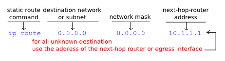
The destination IP address 0.0.0.0 (unknown) represents all destination which cannot be found in the routing table. This address uses the network mask of all zeros (0.0.0.0). As long as the router does not have the best match in the routing table for a given destination ('subnet not in table') the default route is going to be used instead. It is the 'gateway of last resort'. Like previously explained, on point-to-point links you can use the outbound interface instead of the address of the next-hop router.

Applying default routes is going to be easy.

Configuration on R4
Step 1
Packets for all unknown destinations send via R1.

R4(config)#ip route 0.0.0.0 0.0.0.0 s0/2
R4(config)#

Configuration on R5
Step 1
Packets for all unknown destinations send via R2.

R5(config)#ip route 0.0.0.0 0.0.0.0 s0/2
R5(config)#

Simple test will prove the default route operation:

Pic. 8 - Default Route Test.

Even though the routing table does not have the route towards 192.168.5.1, the packets are delivered using the default route (via R1 which knows how to get there).

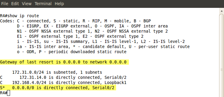
Look what the routing table shows when default route has been added (pic. 9).

Pic. 9 - Routing Table with Default Route.

Static Routing with Primary and Backup Links
In order to spice things up, I am going to configure two additional connections from HQ to our branches using Frame-Relay. These redundant paths must be used as the backup links. They should be used in the case of losing main path via Serial0/2 interfaces (down).

Pic. 10 - Routing Topology with Redundant Paths.

Icons designed by: Andrzej Szoblik - http://www.newo.pl

Please, disregard my configuration of Frame-Relay links for now. I'm going to address WAN protocols in the upcoming posts. I only need the extra connectivity to show you how to handle the primary and backup scenario using static routing.

Frame-Relay Configuration is going to look like this in order to reflect the topology in the pic. 10.

Circuit Between R1 and R5

R1 Configuration:

R1(config)#interface serial0/0
R1(config-if)#encapsulation frame-relay
R1(config-if)#no frame-relay inverse-arp
R1(config-if)#ip address 172.31.15.1 255.255.255.0
R1(config-if)#frame-relay map ip 172.31.15.5 105 broadcast
R1(config-if)#no shutdown
R1(config-if)#

R5 Configuration:

R5(config)#interface serial0/0
R5(config-if)#encapsulation frame-relay
R5(config-if)#no frame-relay inverse-arp
R5(config-if)#ip address 172.31.15.5 255.255.255.0
R5(config-if)#frame-relay map ip 172.31.15.1 501 broadcast
R5(config-if)#no shutdown
R5(config-if)#

Circuit Between R2 and R4

R2 Configuration:

R2(config)#interface serial0/0
R2(config-if)#encapsulation frame-relay
R2(config-if)#no frame-relay inverse-arp
R2(config-if)#ip address 172.31.24.2 255.255.255.0
R2(config-if)#frame-relay map ip 172.31.24.4 204 broadcast
R2(config-if)#no shutdown
R2(config-if)#

R4 Configuration:

R4(config)#interface serial0/0
R4(config-if)#encapsulation frame-relay
R4(config-if)#no frame-relay inverse-arp
R4(config-if)#ip address 172.31.24.4 255.255.255.0
R4(config-if)#frame-relay map ip 172.31.24.2 402 broadcast
R4(config-if)#no shutdown
R4(config-if)#

Now let's get back to the business. If I add two static route entries using the newly created paths, the metric of each of them is going to be identical with the metric used by the primary link (Serial0/2). This way, load balancing (traffic sharing) is going to be used since two equal cost paths exist. Our design stipulates that Frame-Relay circuits should be used as the backup links only (Serial0/2 down).

In order to accomplish this, I should change either the metric or administrative distance of the backup path. Unfortunately, we cannot change the metric (no command available) on static routes, but we can easily increase the value of administrative distance to make the backup path less preferred. The default AD for static routes is 1, so I will make the backup route less trusted by using the value of, say, 3.

Backup Link Between R1 and R5

R1 Configuration:

R1(config)#ip route 192.168.5.0 255.255.255.0 172.31.15.5 3
R1(config)#

R5 Configuration:

R5(config)#ip route 0.0.0.0 0.0.0.0 172.31.15.1 3
R5(config)#
  
Backup Link Between R2 and  R4

R2 Configuration:

R2(config)#ip route 192.168.4.0 255.255.255.0 172.31.24.4 3
R2(config)#

R4 Configuration:

R4(config)#ip route 0.0.0.0 0.0.0.0 172.31.24.2 3
R4(config)#

This way, the primary link (via Serial0/2) is preferred due to the lower administrative distance (AD=1). Look at R4 now:

Pic. 11 - R4's Routing Table with Primary Link UP.

In case the primary link goes down, the extra ip route (using Frame-Relay link) kicks in like shown in the pic. 12.
Pic. 12. - R4's Routing Table with Primary Link DOWN.


In the few upcoming posts, I will focus in on dynamic routing protocols.

Lesson 25 - Switch Port Security


This post is the last one related to layer 2 technologies. With the next posts, I will shift my focus to layer 3 technologies. If you use GNS-3 or dynagen (dynamips emulator), you'll be able to perform all routing tasks on your computer as long as you have IOS image.

Switchport Port Security
This IOS feature (switch only) allows you to limit the number of MAC addresses that will be serviced on a given port. It comes with multiple options such as which MAC address(es) is/are going to be allowed on a given port, and what action should be taken when the violation of the policy occurs. This way, you can further protect your entry point in the network (access switches).

By default, the port security is turned off on all interfaces. In order to turn it on, a port must be in an access mode. Otherwise the command will be rejected. Check out the below attempt of enabling it when the port is in a 'dynamic desirable' rather than an access mode.

Pic. 1 - Port security (switchport port-security) command rejected.

The proper sequence of the commands to enable port security on F0/1 would be as follows:

SW1(config)#interface fastethernet0/1
SW1(config-if)#switchport mode access
SW1(config-if)#switchport port-security

The above configuration applies a default security policy on the port. What settings are going to be used here may vary between switch platforms. But typically, the port in a secure mode allows only aSINGLE MAC address (just one) to be serviced and in the case when the violation occurs, the port will be put in ERR-DISABLE state. This state will put the port down so, no traffic can traverse it.

For the purpose of my presentation, I will use very simple topology (Pic. 2).

Pic. 2 - Topology
Icons designed by: Andrzej Szoblik - http://www.newo.pl

My router R1 is connected to SW1 port F0/1. The MAC address of the R1 (E0/0 port) is:
0050.500f.6600

Now, I want accomplish the two goals:

  • R1 E0/0 port should be connected to SW1 port F0/1. In case, the R1 is connected to any other port on this switch, the communication with the R1 should not be allowed.
  • SW1 port F0/1 should service traffic to/from R1 E0/0 interface. In case, somebody connects more devices to port F0/1 than R1 port E0/0, and/or different device, the port F0/1 should be put in an ERR-DISABLE state.
Let us go ahead and configure it!

I need to show you what the current status of the SW1 port F0/1 is, before we apply port security.

Pic. 3 - SW1 port F0/1 Before Security is applied

As you see, the MAC address of the R1 E0/0 interface has been learned dynamically from the incoming frames on SW1 port F0/1. At this stage, I must explain the difference between dynamic and static entries in the MAC address table.
  • DYNAMIC - the entry is created from the incoming frames by reading the source MAC address field in the Ethernet header. The entry is valid for 5 minutes (300 seconds) by default. If the host with this source address (here R1) does not send any frame towards the port of the SW1 for 300 seconds, the entry is removed. Every time, the R1 sends a frame towards the SW1 F0/1, the entry timer is reset, or if the entry has already been removed, the same MAC address is mapped to the port again.
  • STATIC - the entry (MAC address) is permanently mapped to a specific port. It does not age like a 'dynamic' entry. The switch does not create this MAC address to port mapping by reading the source MAC address, but it is the administrator of the switch that creates it in the global config mode using 'mac address-table static' command.
 So, the question is: what is the difference in operation if you use static over dynamic method?
In case of static mapping of MAC address to a port, you CANNOT move this device to any other port as it will not work! The switch expects to receive the frames sourced from the device on the specific port. If it receives the frames with the MAC address on different port than assigned statically, it will drop the frames from that device.

If you rely on dynamic address learning (default), you can plug in a device to any port and quickly the switch flushes the entry from the old port (where the device was connected previously) and re-learns the MAC address on the new port you have just connected your device to.

Knowing that, we can proceed with our security plan now. I have applied the port access and port security commands like presented above. Now, take a look at the default settings applied on this specific switch platform I use (Catalyst 2950). Bear in mind, that your switch may have different default settings.

Pic. 4 - Port in Secure Mode.

Quick dissection of the output's essential information:
  • Secure Port - F0/1 is now working in a secure mode.
  • MaxSecureAddr - The maximum number of addresses allowed on this port is 1 MAC address.
  • CurrentAddr - At this moment, this maximum limit has been reached.
  • SecurityViolation - Currently there's been no security violation reported.
  • Security Action - In case there is a security violation detected, the port will go DOWN (err-disable).
Let's see which MAC address is now in the secure mode (it should be R1 E0/0).
Pic. 5 - Current Secure MAC Address.

Everything seems good so far. F0/1 port learned dynamically the MAC address of our R1, and is now considered a secured MAC address. One of our two goal plan seems to be working. What if we moved the R1 to another port? What would happen then?

Pic. 6 - MAC address with security enabled.

This specific switch (C2950) has also made the entry 'static' which means, that if you move R1 E0/0 port to another port of this switch, the traffic from R1 will be discarded!

Well, you can further improve the security of your R1. The problem is, that with current configuration, you can reboot the switch and while doing so, you can plug in a different device to F0/1. This way the newly learned MAC address upon reload of the switch becomes the secure one. 

In order to make it more secure, it is recommended that you configure the secure MAC address permanently. Just like in the example below:

SW1(config)#interface f0/1
SW1(config-if)#shutdown
SW1(config-if)#switchport port-security address 0050.500f.6600
SW1(config-if)#no shutdown
SW1(config)#end
SW1(config)#wr

Pay attention to some of the commands presented. I shut the port down first to flush the current (the same) MAC address. Otherwise this command would be rejected (duplicate MAC address). Then, after adding the MAC address, I brought the port up and saved my configuration.

Now, the MAC address becomes the part of configuration and the security applied can withstand the reboot of the switch.

Pic. 7 - Configuration saved in NVRAM.

There is one more command that offers more detailed output (pic. 8).

Pic. 8 - Port security detailed output

Take a look at some interesting options shown below:

Pic. 9 - Port security options.

  • Aging - there are two types of secure MAC address aging: 'absolute' and 'inactivity'. The former, allows to specify how long the MAC address should be considered secure, the latter decides that MAC address is no longer secure if it is not transmitting data in a given time. Both parameters can be configured but, as per default, the secure MAC addresses do not age.
  • Mac-address - like in my configuration, this option specifies which address is to be secured. You can type in a specific MAC address (like I did) or use a 'sticky' keyword. When 'sticky' is used the MAC address(es) already learned on the port become part of the interface's configuration. However, adding MAC address manually is recommended. Just like I did.
  • Maximum - how many MAC addresses can be considered secure on a given port (platform dependent). The default is: 1.
  • Violation - this option allows to choose one of the three options as to what action must be taken if the violation of the security is detected. 
Port Violation Actions
  1. Protect - when the port receives the traffic from the MAC addresses which are not configured as secure, it silently drops those transmissions. There is NO notification logged about the violation occurring on a port.
  2. Restrict - similar to 'protect' only the switch logs the violations detected.
  3. Shutdown (default) - the port will transition to err-disable upon detecting the violation.
Let me quickly show you what happens if my switch detects the violation of the port security.

I am going to change the MAC address on my E0/0 port of R1 to:
0000.aaaa.aaaa

As a result of that, the first frame sent towards the SW1 F0/1 will cause the violation of my policy (wrong MAC address, and the port allows only one MAC address previously assigned as the secure one).

Pic. 10 - The log generated after violation on the port occurred.

Below is the status of the port now.
Pic. 11 - Port in err-disable state upon violation of security.

The only way to rectify the situation is to do the following:
  1. Plug in the device with the right (secure) MAC address back to the port F0/1.
  2. Shut the port down manually (administrative mode shutdown).
  3. Bring the port up using: 'no shutdown' command.
This way has one major disadvantage. Well, it seems you have to perform the three steps mentioned above which looks like you are being punished for somebody else's security violation.

You can configure two additional commands in the global configuration mode which allow your switch to attempt to bring the port automatically after a period of time in err-disable mode. If the proper device is already connected, the port will be fully functional again.

SW1(config)#errdisable recovery cause psecure-violation
SW1(config)#errdisable recovery interval 60

The first command instructs the switch to pay attention to any ports in err-disable state. If such ports exist, the switch will attempt to bring them up after 60 seconds of putting the in err-disable mode (second command).

In my next post, we will start talking about layer 3. I propose that we refresh our knowledge of binary system which is essential to understand IP addressing scheme.

Mar 11, 2013

Lesson 16 - VLANs In Practice


Lesson 15 introduced another layer 2 concept called VLANs (Virtual Local Area Networks). If you understand their purpose, it is time to get the juices flow by configuring them.

In this post, I am going to show you how to configure VLANs in a simple design, routing between VLANs and how to verify their operation. I am going to use the following network topology to accomplish our goals (Pic. 1).

Pic. 1 - VLAN Topology
Icons designed by: Andrzej Szoblik - http://www.newo.pl


NOTICE!
In my testing topology (pic.1) I have already configured the management VLAN (500), for the purpose of accessing the switches and R1 remotely from my computer.

VLANs 10 and 20 as well as the R1 routing configuration have not been configure yet. This is going to be our main task in this lesson.


Before we begin, take a closer look at the the topology (click at the picture to enlarge it). Please, pay a special attention to the IP addresses of the computers. Have you noticed that they belong to two DIFFERENT layer 3 networks? The blue numbers below denote the network address and they are different. If you are not familiar with IP addresses, and you have no clue what I'm talking about, don't worry. I'm going to explain those in the upcoming lessons.  

  • PC1 address is 192.168.10.1 255.255.255.0 
  • PC2 address is 192.168.20.1 255.255.255.0

For now though, take for granted that if computers are members of different layer 3 networks, the applications installed on them cannot communicate without a router.

Okay, it's time to type in our first command: show vlans.

Pic. 2 - 'show vlans' command.

The output (Pic.2) gives you a plethora of information. Take a closer look and then read on to know what you're looking at.

  1. VLAN - This column shows all VLANs that exist in a switch database. In the case of my switch, there is only one VLAN I have created (VLAN 500). I've named it HOME_LAN. I use it be able to access my equipment using Telnet. All other VLANs listed exist on a switch by default. You can safely ignore these as they are not even supported by the switch (VLANs 1002-1005). Important is VLAN 1, which is the default one. All interfaces belong to VLAN 1 by default.
  2. Name - This column lists the names given to VLANs. Switches use numbers to differentiate between VLANs, not names. You name VLANs using friendly names, so we know which VLAN number is which group. If you do not give a name to a newly created VLAN, the default name is given (e.g. Vlan0002 for VLAN 2, Vlan0003 for VLAN 3 etc.).
  3. Status - It tells you what VLANs are active and supported by a switch. If you delete VLAN from the database, and the port is still configured as member of this VLAN, the port is not going to forward any frames. Default VLAN (VLAN=1) CANNOT be removed. You can try, but it won't work.
  4. Ports - The last column, shows which ports belong to VLANs. Simple as that. In order to change VLAN's membership of the interface, you have to do it manually.
Below, you can see some additional parameters related to the VLANs such as MTU (Maximum Transmission Unit), which for Ethernet is 1500 bytes.

A more handy command is: show vlan brief. Take a look at its output (pic. 3).

Pic. 3 - 'show vlan brief' output.

This is probably more often used command if you want to check the VLANs and port membership.

Interfaces have default settings which are not seen in the running configuration:
show running-config.

In order to verify what are the default settings of the interface use the following command (here interface f0/1 is used):
show interface f0/1 switchport.

Familiarize yourself with the output of this command. Pay a special attention to the lines I highlighted.

Pic. 4 - 'show interface f0/1 switchport' output.


Recall from the previous lesson (Lesson 15) the two types of the ports used in VLAN infrastructure: trunk and access. I need to ramble a tad more before we proceed to the configuration.

  1. Administrative Mode: dynamic desirable - This option means that the port is running Dynamic Trunk Protocol (DTP). Port int this mode (the default setting on this particular switch), will send special frames to the device connected to it, trying to negotiate trunk connection. If the other end responds to this proposal, both interfaces become trunks. Since in my case, it is a PC that is connected to port F0/1, and did not respond to this negotiation (no DTP), the port became a 'static access' (member of one VLAN only).
  2. Operational Mode: static access – This tells you what the real mode of the port is. Here, the interface did not negotiate trunk connections so automatically became an 'access' interface.
  3. Negotiation of Trunking: On – This option informs you, that the DTP protocol is active on the interface. The port will be sending DTP frames out trying to negotiate trunk mode.
  4. Access Mode VLAN: 1 (default) – Since the interface did not become trunk, and there is no manual configuration regarding the VLAN it should belong to, the interface ended up as a member of the default VLAN (VLAN 1).
  5. Trunking VLANs Enabled: All – In case the interface transitions to a trunking mode, ALL VLANs are going to be allowed on this interface (1-4094).

Now, it is time to define our configuration tasks and complete our mission.

CONFIGURATION STEPS

Given the topology diagram (pic. 1), configure the following:
  1. Configure end-to-end VLANs (the same set of VLANs on all switches).
  2. Assign ports to VLANs.
  3. Create an unconditional trunking between the switches.
  4. Enable routing between VLANs using 'router on a stick' (yes, it is a real name of this method).
SOLUTION
Step 1
Configure end-to-end VLANs (the same set of VLANs on all switches).

On SW1:
SW1#configure terminal
SW1(config)#vlan 10,20
SW1(config-vlan)#exit
SW1(config)#

On SW2:
SW2#configure terminal
SW2(config)#vlan 10,20
SW2(config-vlan)#exit
SW2(config)#

On SW3:
SW3#configure terminal
SW3(config)#vlan 10,20
SW3(config-vlan)#exit
SW3(config)#

Verification
On all switches you should see the VLANs created (here SW1 output).

Pic. 5 – VLANs in the database

Steps 2
Assign ports to VLANs.

Since we are going to use port-to-vlan assignment (recommended in most cases) , this option puts the ports permanently in a given VLAN and disables DTP.

On SW1:
SW1(config)#interface f0/1
SW1(config-if)#switchport mode access
SW1(config-if)#switchport access vlan 10
SW1(config-if)#exit
SW1(config)#

On SW2:
SW2(config)#int f0/1
SW2(config-if)#switchport mode access
SW2(config-if)#switchport access vlan 20
SW2(config-if)#exit
SW2(config)#

Explanation!
The command: 'switchport mode access' puts the port in an unconditional 'access mode' in which DTP is turned off. The port CANNOT become trunk anymore.

The command: 'switchport access vlan 10' places the interface in VLAN 10 (broadcast domain). From now on, the port can communicate with other hosts in VLAN 10 but not other VLANs.

Verification (here only SW1 output)

Pic.6 – show vlan brief

As you can see the port f0/1 is now a member of VLAN 10.

Step 3
Create an unconditional trunking between the switches. 


NOTICE!
The trunking should be enabled on ports f0/15, f0/16 and also on f0/1 since this port will use trunking mode to connect multiple R1's sub-interfaces ('router on a stick') for the purpose of routing unicast between VLANs 10 and 20.

Also, in my case SW3 is Catalyst 2950 which supports only DOT1q protocol. That is why the command 'switchport trunk encapsulation' does NOT exist on this switch. I will use that command on SW1 and SW2 though, in order to select this type of trunking protocol.


On SW1:

SW1(config)#interface range f0/13 - 15
SW1(config-if-range)#switchport trunk encapsulation dot1q
SW1(config-if-range)#switchport mode trunk
SW1(config-if-range)#exit
SW1(config)#

On SW2:

SW2(config)#interface range f0/13 - 14 , f0/16
SW2(config-if-range)#switchport trunk encapsulation dot1q
SW2(config-if-range)#switchport mode trunk
SW2(config-if-range)#exit
SW2(config)#

On SW3:

SW3(config)#interface range f0/1 , f0/15 - 16
SW3(config-if-range)#switchport mode trunk
SW3(config-if-range)#exit
SW3(config)#

Verification (here SW1 only):

Pic. 7 – show interface trunk

An alternate method of verifying trunk ports is shown below. However, this way you can see one port at a time. But the output is more verbose.
Pic. 8 – 'show int f0/15 switchport'

Step 4
Enable routing between VLANs using 'router on a stick'.

On R1:

R1(config)#
R1(config)#int f0/0
R1(config-if)#no ip address
R1(config-if)#no shutdown
!
Create sub-interface with IP address to be gateway for VLAN 10.
R1(config-if)#int f0/0.10
R1(config-subif)#encapsulation dot1q 10
R1(config-subif)#ip address 192.168.10.254 255.255.255.0
R1(config-subif)#
!
! Create sub-interface with IP address to be gateway for VLAN20.
R1(config-subif)#int f0/0.20
R1(config-subif)#encapsulation dot1q 20
R1(config-subif)#ip address 192.168.20.254 255.255.255.0
R1(config-subif)#end
R1#

Verification
The ultimate test to verify the connectivity between VLANs is to use ping utility and check if PC1 talks to PC2. If successful, it is proving that our configuration is correct.

The routing table on R1 should show you that router knows both networks: 192.168.10.0/24 and 192.168.20.0/24 (pic. 9). So it can transmit the packets between these two.

Pic. 9 - Routing Table on R1

Soon, video is going to be available with the above configuration and additional options for inter-VLAN routing.

In my next post, we will look at what is really happening 'behind the curtain'. I will show you the traffic flow using our VLAN's configuration step by step.