Showing posts with label mask. Show all posts

Mar 13, 2013

Lesson 49 - Packet Filtering with Extended ACLs


This post I start with presenting solution to the Task 2 I left unanswered in the lesson 49.

Task 2
Configure an IP standard ACL that denies packets coming from the host 172.31.123.3 going towards 192.168.5.0/24. Traffic from other sources should be allowed. 

Again, we use the standard IP ACL here, which is going to be applied on R5. Here goes:

R5 Configuration:

!
In the global config 
!
access-list 1 deny host 172.31.123.3
access-list 1 permit any
!
Enter the the incoming interface and apply the access-list
!
interface serial0/2
 ip access-group 1 in
!

Notice!

  • access-list 1 - ACL numbers 1-99 are IP standard ACLs (check source of the packets only.
  • host 172.31.123.3 - this keyword is an alias for: 172.16.123.3 0.0.0.0. It is a source address of the packets being inspected.
  • any - this keyword is an alias for: 0.0.0.0 255.255.255.255 - any source here.
I hope your answers were correct. Now is the time to learn Extended ACLs.

First, look at the syntax you see in Cisco documentation:

Pic. 1 - Extended ACL Syntax.

If you go like: 'OMG!' do not worry because you do not have to use all these keywords.

The options we are going to use can be presented as follows:

Pic. 2 - Extended ACL Common Syntax.
It looks a bit more convoluted but do not worry because in time you will feel quite confident with it. Your best friend is help '?' which is going to show you what options and arguments are required.

The best way to explain the syntax you need to get familiar with is to use an example and try to de-construct it. So, let's look at our topology one more time and create the following filter:

Task 1
Deny telnet sessions coming from 192.168.4.0/24 destined to 172.31.3.0/28 and 172.31.3.16/28. All other traffic should be allowed.

Pic. 3 - Topology.
Icons designed by: Andrzej Szoblik - http://www.newo.pl

Which ACL type should we use?
Since, we are very specific in terms of which protocols we want to deny, we must use Extended ACL. The standard ACL can only match on the source IP address, permitting or denying all protocols the packet is carrying.

Which router/interface should we apply the ACL on?
Our topology clearly shows that R3 has three different interfaces with three different addresses. So, we have two options here:

  • We can configure an Extended ACL on R4 FastEthernet 1/0 interface in the inbound direction (close to the source as per ACL guideline)
  • We can configure an Extended ACL on R4 Serial0/2 in the outbound direction.
  • Alternatively, we can apply an Extended ACL on R3 FastEthernet1/0 (inbound).
I'm going to chose the option suggested by the ACL guide lines: as close to the source as possible.

Let's read the task again:


Task 1

Deny telnet sessions coming from 192.168.4.0/24 destined to 172.31.3.0/28 and 172.31.3.16/28. All other traffic should be allowed.

Here's one way to configure this:

R4 Configuration:

!
In the global 'config' mode the statements are:
!
access-list 100 deny tcp 192.168.4.0 0.0.0.255 172.31.3.0 0.0.0.15 eq 23
access-list 100 deny tcp 192.168.4.0 0.0.0.255 172.31.3.16 0.0.0.15 eq 23
access-list 100 permit ip any any
!
Apply the ACL on the interface
!
interface FastEthernet 1/0
  ip access-group 100 in
!

Three lines that 'deny' traffic are similar. Let's dissect its syntax:

access-list 100 deny tcp 192.168.4.0 0.0.0.255 172.31.3.0 0.0.0.15 eq 23

  • access-list 100 - The extended ACL (numbers 100-199)
  • deny - condition (either 'deny' or 'permit' are allowed)
  • tcp - layer 3 or 4 protocol (such as: ipicmptcpudpripeigrp etc.)
  • 192.168.4.0 - source IP address
  • 0.0.0.255 - source wildcard mask (inversed mask)
  • 172.31.3.0 - destination IP address
  • 0.0.0.15 - destination wildcard mask (inversed mask)
  • eq - operator: eq (equal), lt (less than), gt (greater than), range
  • 23 - destination port (telnet)
Notice!
After source wildcard there is no source port. This means that the source port is not inspected at all (disregarded).

In the next post I'm going to show you few examples of extended ACL which should reinforce your study

Lesson 45 - EIGRP Fundamentals Part 3 - The Lab


In this post I'll put the pieces together in the practice lab. Our topology will be as presented below:
Pic. 1 - Topology Diagram.
Icons designed by: Andrzej Szoblik - http://www.newo.pl

This post is going to collect bits and pieces from lessons 43 and 44 to show you the implementation on the command line interface with verification steps.

Task List

General requirements

  • All routers must use Autonomous System 1.
  • All networks/subnets must be advertised and reachable.
  • EIGRP authentication should be enabled between R1 and R4.
  1. Enable EIGRP between R1R2 and R3. Make sure loopbacks are advertised. Use the most specific wildcard mask.
  2. Enable EIGRP between R1 and R4. Make sure loopbacks are advertised. Use the most specific wildcard mask on R1. On R4 the network statement should be classful (no wildcard mask).
  3. Enable EIGRP between R2 and R5. Make sure loopbacks are advertised. Use the most specific wildcard mask on R2. On R5 the network statement should be classful (no wildcard mask).
  4. Enable EIGRP authentication between R1 and R4. Use the password 'cisco'.

Lab Solution

Step 1
Enable EIGRP between R1R2 and R3. Make sure loopbacks are advertised. Use the most specific wildcard mask.

Note!
The 'no auto-summary' keyword is not necessary in my topology, but I include it to show you how to disable automatic summarization to the class boundary.
R1 Configuration:

!
R1(config)#router eigrp 1
R1(config-router)#no auto-summary
R1(config-router)#network 172.31.123.1 0.0.0.0
R1(config-router)#network 172.31.1.1 0.0.0.0
R1(config-router)#
!

R2 Configuration:

!
R2(config)#router eigrp 1
R2(config-router)#no auto-summary
R2(config-router)#network 172.31.2.1 0.0.0.0
R2(config-router)#network 172.31.123.2 0.0.0.0
R2(config-router)#
!


Pic. 2 - EIGRP Adjacency Between R1 and R3.


R3 Configuration:

!
R3(config)#router eigrp 1
R3(config-router)#no auto-summary
R3(config-router)#network 172.31.3.1 0.0.0.0
R3(config-router)#network 172.31.3.17 0.0.0.0
R3(config-router)#network 172.31.123.3 0.0.0.0
R3(config-router)#
!

Verification:

Pic. 3 - R3's EIGRP-enabled nterfaces.
Pic. 3 confirms the network statement was correct for each interface.
Pic. 4 - R3's EIGRP Neighbor Table.

Notice!
R3 heard EIGRP hello packets from two neighbors. But to be sure they have exchanged their topology tables, the 'Q Cnt' column must show '0' messages pending (not acknowledged).

Notice!
In the 'output explanation' I show only the most relevant pieces of information. Others are either self-explanatory or not necessary to understand at the CCNA level.

Output Explanation:

  • H - Handle; shows order in which the neighbors were discovered and adjacency built between them.
  • Address - The IP address of the neighbor.
  • Interface - The  local interface where neighbors are discovered.
  • Hold - Length of time in seconds how long the router is going to wait for hello packet before declaring the neighbor down.
  • Uptime - Elapsed time since the local router first heard from the neighbor.
  • SRRT - Smooth Round Trip Timer; amount of time in milliseconds the required to send the packet to the neighbor and receive the acknowledgement.
  • RTO - Retransmit Time Out; amount of time in milliseconds the local router waits before retransmitting EIGRP packet if acknowledgement did not arrive.
  • Q Cnt - The number of EIGRP packets (update, query, reply) that the router keeps in the queue to be sent. Typically, it implies that some EIGRP reliable packets have not been acknowledged.
Pic. 5 - R3's EIGRP Topology Table.

Output Explanation:
  • P - Route is Passive which means that router is not actively looking for a path towards it. It is a required status in stable topology.
  • FD - Feasible Distance (metric value towards the destination)
  • (156160/128256) - The first number (156160) is FD, the second number (128256) is the Advertised Distance advertised by the neighbor (FD of the neighbor). Recall, the Feasibility Condition from the previous lessons.
Pic. 6 - R3's Routing Table.

Output Explanation:
  • D - EIGRP learned prefix; 'show ip route' shows all prefixes including connected networks with explanation of codes.
  • [90/156160] - The first number (90) is the Administrative Distance (trustworthiness) of the protocol, the second number (156160) is the metric based on best FD from the topology table.
  • via 172.31.2.1 - next-hop router (neighbor that advertised it).
  • 00:30:04 - how long ago the prefix was learned.
  • FastEthernet1/0 - The outbound interface towards the destination.
Pic. 7 - R3's EIGRP Details.
Your homework:
look at pic. 7 and consult my previous posts about EIGRP and the topology diagram to understand the highlighted parts.


Step 2
Enable EIGRP between R1 and R4. Make sure loopbacks are advertised. Use the most specific wildcard mask on R1. On R4 the network statement should be classful (no wildcard mask).

R1 Configuration:

!
R1(config-router)#network 172.31.14.1 0.0.0.0
R1(config-router)#
!

R4 Configuration:

!
R4(config)#router eigrp 1
R4(config-router)#no auto-summary
R4(config-router)#network 172.31.0.0
R4(config-router)#network 192.168.4.0
R4(config-router)#
!


Verification should be performed after this step (look at step 1).

Step 3
Enable EIGRP between R2 and R5. Make sure loopbacks are advertised. Use the most specific wildcard mask on R2. On R5 the network statement should be classful (no wildcard mask).

R2 Configuration:

!
R2(config-router)#network 172.31.25.2 0.0.0.0
R2(config-router)#
!


R5 Configuration:

!
R5(config)#router eigrp 1
R5(config-router)#no auto-summary
R5(config-router)#network 192.168.5.0
R5(config-router)#network 172.31.0.0
R5(config-router)#
!

Verification should be performed after this step (look at step 1).

Step 4
Enable EIGRP authentication between R1 and R4. Use the password 'cisco'.

R1 Configuration:

!
R1(config)#key chain MY_EIGRP_KEY
R1(config-keychain)#key 1
R1(config-keychain-key)#key-string cisco
R1(config-keychain-key)#
R1(config-keychain-key)#int s0/2
R1(config-if)#ip authentication key-chain eigrp 1 MY_EIGRP_KEY
R1(config-if)#ip authentication mode eigrp 1 md5
!


R4 Configuration (without prompts):

!
key chain MY_EIGRP_KEY
 key 1
   key-string cisco
!
interface Serial0/2
 ip address 172.31.14.4 255.255.255.0
 ip authentication mode eigrp 1 md5
 ip authentication key-chain eigrp 1 MY_EIGRP_KEY
!

Verification: 
Pic. 8 - R1's Neighbors.

R1 and R4 have re-established neighbor relationships.

In the next post, I'll present a few troubleshooting techniques based on the topology and configuration used in this lesson.

Mar 12, 2013

Lesson 41 - OSPF Fundamentals Part 4 - Implementation


In this post, I'm going to present the commands and verification steps with regards to OSPF implementation in a single area. Configuration will also include the authentication of OSPF packets.

If you want to go fancy with OSPF the configuration can be quite challenging. Configuring basic OSPF in a single area is very simple though. There are two basic steps required:

  1. Enable OSPF in the 'config' mode.
  2. Instruct the OSPF process which interfaces should be enabled for OSPF and in which areas the links should operate.
Here is the simple topology we are going to use to see the configuration steps.
Pic. 1 -  Topology Diagram.
Icons designed by: Andrzej Szoblik - http://www.newo.pl

OSPF Basic Configuration
The commands which enables OSPF on an interface can look like the below.

Pic. 2 - Example of OSPF Configuration.
router ospf 1 - This command starts the OSPF process 1 on R1.
network 10.1.0.0 0.0.255.2555 area 0 - This statement enables OSPF process on all interfaces which IP addresses are 10.1.x.x (where x.x can be any number as the last two bytes are not checked by the wildcard mask).

What is the wildcard mask in the above statement?

Wildcard mask is an inversed network mask. The bits in the wildcard mask which are set to '0' will check the corresponding bits in the IP address. The bits in the wildcard mask which are set to '1' will ignore the corresponding bits in the IP address.

Pic. 3 - OSPF Wildcard Mask.
Look at the Pic. 2 again. According to the network statement, OSPF will be enabled on F1/0 and S0/1 of R1 (pic. 1).

What network statement could we use in order to enable OSPF on s0/1 interface but not on F1/0?

I can give you a couple of examples. Remember that wildcard mask will use '0s' to check bits in the address and '1s' will ignore them.

Example 1

R1(config)#router ospf 1
R1(config-router)#network 10.1.13.0 0.0.0.255 area 0

This way the wildcard bits are going to check if there are any interfaces which use IP addresses according to 10.1.13.x (where x is any number). These will be OSPF-enabled.

Example 2

R1(config)#router ospf 1
R1(config-router)#network 10.1.13.1 0.0.0.0 area 0

The second example will enable OSPF on the interface that has the EXACT IP address 10.1.13.1. The wildcard bits consists of all '0s' so ALL the corresponding bits in the IP address used must match in order for the interface to be running OSPF protocol.

As you already know, the moment we enable OSPF on an interface, the routing process begins to send the 'hello' packets trying to discover the neighbor(s). If they are discovered the system begins to check parameters in the OSPF header and hello packet. If they agree on the mandatory fields (hello/dead intervale etc.) the are going through several phases to finally synchronize their LSDBs.

Of course, the network statement with wildcard mask does not influence what network mask is going to be advertised along with the IP address. OSPF, being a classless routing protocol, will advertise their networks/subnets as per configuration on the interfaces.

So, let's configure OSPF as per topology diagram (pic. 1) and observe the process of reaching the FULL state (adjacency) using the debug. I will use the most specific wildard mask here but you already know there are a lot of options available to start OSPF on the interfaces.

R1 Configuration:

R1(config)#router ospf 1
R1(config-router)#network 10.1.1.1 0.0.0.0 area 0
R1(config-router)#network 10.1.13.1 0.0.0.0 area 0
R1(config-router)#network 172.16.101.1 0.0.0.0 area 0
R1(config-router)#

R3 Configuration:

R3(config)#router ospf 1
R3(config-router)#network 10.1.3.3 0.0.0.0 area 0
R3(config-router)#network 10.1.13.3 0.0.0.0 area 0
R3(config-rotuer)#network 172.16.103.3 0.0.0.0 area 0
R3(config-router)#

Now, here's the output of the debug statement on R3. Pay attention to the highlighted words and compare them with the OSPF Neighbor State Machine (lesson 38 in the archive of this blog). 

Pic. 4 - Debug IP OSPF Events on R3.
Notice, that it is a point-to-point network, so there is no election of DR and BDR roles.

As part of practical exercise, try to use the same debug in you lab on routers connected using broadcast (Ethernet) links. Watch for DR/BDR election.

OSPF Verification Commands
It is important to be able to perform some basic verification steps. Here are the commands that you will use most often.

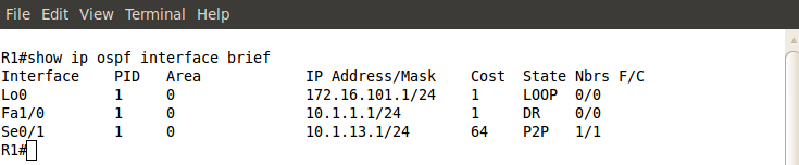
First, let's check if our network statement was correct (OSPF is enabled on the appropriate interfaces).

Pic. 5 - OSPF-enabled Interfaces.

You can also see a detailed output which shows more information with regards to OSPF running on an interface. Check it out.
Pic. 6 - OSPF-enabled Interface Detailed Output (Fa1/0).


Then, I want to make sure that R1 is in FULL state with R3. Here's my command:

Pic. 7 - OSPF Neighbor Check.

Two more commands will be useful as well. First one showing the brief output of LSDB (more detailed output is beyond the scope of this tutorial).

Pic. 8 - OSPF Database.

Notice that both R1 and R3 advertise four links. The loopback0, F1/0, and S0/1 which counts as two links (point-to-point interfaces are advertised as two: the IP address of the next hop and the subnet/network IP).

And finally, the content of OSPF routing table:

Pic. 9 - OSPF Routing Table.

OSPF Authentication
As part of implementation we can authenticate OSPF packets to prevent some rouge routers joining our OSPF domain. If someone configures and plugs in the router, it won't become adjacent with others in the domain unless the right method and password are used.

There are two methods to authenticate OSPF packets:

  1. Simple Password - The password is sent in the clear text format.
  2. MD5 - The password is not sent at all. The digest is created using the shared password between neighbors.
Both methods can be implemented using two different ways.

Let's start with Simple Password method.
Method 1 (password must match on both routers; here: S3cr3t)

R1(config)#router ospf 1
R1(config-router)#area 0 authentication
R1(config-router)#exit
R1(config)#interface serial0/1
R1(config-if)#ip ospf authentication-key S3cr3t

Method 2

R1(config)#interface serial0/1
R1(config-if)#ip ospf authentication
R1(config-if)#ip ospf authentication-key S3cr3t
R1(config-if)#

The first command enables OSPF authentication using Simple Password method (area 0 authentication or ip ospf authentication)

The second command specifies the password that is going to be used (ip ospf authentication-key)

In the first method, OSPF authentication is enabled on ALL interfaces configured to operate in area 0. The second method allows more control as to which interfaces will be sending authenticated OSPF packets.

Pic. 10 - Simple Password Authentication Enabled.

MD5 method can also be configured in two ways.
Method 1 (password must match on both routers; here: S3cr3t)
R1(config)#router ospf 1
R1(config-router)#area 0 authentication message-digest
R1(config-router)#exit
R1(config)#interface serial0/1
R1(config-if)#ip ospf message-digest-key 1 md5 S3cr3t

Method 2

R1(config)#interface serial0/1
R1(config-if)#ip ospf authentication message-digest
R1(config-if)#ip ospf message-digest-key 1 md5 S3cr3t
R1(config-if)#

Both the password (here: S3cr3t) and the key number (here: 1) must match between the neighbors.

Use: show ip ospf int s0/1 to check MD5 authentication.

You might try out the following two commands and see what they show: 

R1#show ip protocols
R1#show ip ospf

The next post is going to be the last one in the OSPF series. We are going to configure OSPF in the more complex topology as well as use some troubleshooting techniques to fix the common configuration issues.

Lesson 30 - IPv4 Subnetting - Practice


In the previous post, I showed you three major rules used in calculating subnets. This knowledge can only be verified in practice though. Let me show you a few examples related to subnet calculations. I hope that looking at this topic from different angles is going to help you understand the concept better and feel confident when planning your IP addressing scheme. The first four questions are merely appetizers for a bigger dish: VLSM.

I am going to refer to my previous post's rules while answering the questions (rule 1, rule 2 and rule 3).

If you still do not remember the weights of all bits, you may consider using this little aid presented below (pic. 1) while calculating subnets, and converting binary network masks into decimal values.

Pic. 1- Subnet Calculation Aid.

This tool is useful before you remember all the weights from left to right and right to left.
Pic. 2 - Example of Subnet Binary-to-Decimal Conversion.

Question 1
Given the prefix 192.168.1.0/24, what should be the length of subnet mask allowing up to 9 subnets?

Answer 1
The address belongs to the class C and uses its default network mask. That leaves us with 8 bits to play with (the last byte). Before we change anything, our address and network mask converted into the binary notation look like shown below (pic. 3).
Pic. 3 - 192.168.1.0/24 in Binary.

In order to create 9 subnets we must extend the existing length of the network mask by 4 bits which allows up to 16 subnets (use calculation aid in pic. 1). If I tried to extend it by 3 bits only, the maximum subnets allowed would be only 8 subnets (rule 2 in lesson 29). So, I must use 4 bits and the result is: 192.168.1.0/28 (192.168.1.0 255.255.255.240).

Pic. 4 - The Answer to Question 1

Question 2
Given the host address 192.168.1.177/29, what are the subnet and broadcast addresses?

Answer 2
In order to determine the subnet and broadcast address of the subnet of this host address, we must look at the length of the network mask first. It is 29 bits (24+5). This tells us that the last byte of the address has 5 bits masked (subnet bits) and 3 bits unmasked (host bits). It is a good idea to look at the the last byte of the address (177) with its network mask using binary notation. Pic. 5 below shows you this clearly.
Pic. 5 - 192.168.1.177/29 in Binary.
Since we must determine the the subnet in which the host resides (177 = 10110001), the host portion of the prefix (host bits reside in the last byte) must all be set to '0'. The byte value with the host zeroed is the address of the subnet (rule 1 pkt.1 in lesson 29). This is the result:

Pic. 6 - Host Bits Zeroed = Subnet Address.

The second part of the question relates to the broadcast address of the subnet. As you remember, in order to obtain the broadcast address, you must put '1' on all host bits of the subnet/network. The subnet has already been determined (pic. 6), so let's put '1' on all bits of the host portion:
.10110111
.10110000 = 176 <- subnet address
..00000111 = 7 <- host bits set to '1'

In decimal it is: 176 + 7 = 183
The broadcast address is: 183.

The below picture illustrates it using binary numbers.

Pic. 7 - Host Bits Set to '1' = Broadcast Address.

Question 3
Given the  prefix 172.16.0.0/17, how many subnets can you create?

Answer3
This is a bit tricky isn't it? In order to answer this question, you don't need any calculator, paper or pen. You must trust the rule 2 in lesson 29. The address and its network mask (called prefix) converted into binary look like presented below:
Pic. 8 - The Number of Subnets for 172.16.0.0/17

As you see the number of bits we have extended the class B address is: 1. So, the number of subnets we can create with it is: 2 subnets, since this subnet bit can be either 1 or 0.
Pic. 9 - Questions 3 Answer

Question 4
What length of network mask would be the most optimal for router's point-to-point connection?

Answer 4
The key to this question is to understand that point-to-point connection needs only 2 host addresses (two points that are connected together). Knowing this, the rest is a piece of cake. We use rule 3 inlesson 29 to determine the length of the network mask that allows 2 host addresses. Check out the picture 10.
Pic. 10 - Calculating Point-to-Point Connection Host Addresses.
If you count ones above the optimal network mask for point-to-point connection is /30. The decimal value is: 255.255.255.252.
Question 5 - Variable Length Subnet Masking (VLSM)
It's time for a big one. Given the topology (pic. 11), calculate IP addresses for each subnet trying to optimize them according the host address requirements. The IP address you should use to create subnets is: 192.168.1.0/24. The number of host addresses in the subnets are as follows:
Subnet 1 = 46 host addresses
Subnet 2 = 16 host addresses
Subnet 3 = 10 host addresses
Subnet 4 = 2 host addresses
Subnet 5 = 2 host addresses

Pic. 11 - VLSM Topology.

Icons designed by: Andrzej Szoblik - http://www.newo.pl

As always, if you know the rules and the method, it is going to be easy thing to do. The rules have been discussed in lesson 29, so let me go about this kind of task now.


NOTICE!
If your design looks similar to mine (optimizing addresses to the number of host required) you muststart the calculation with the largest number of host addresses requirement and work your way down to the least number of host addresses.


This is one of the many methods available. It helps quickly calculate all subnet ranges without using calculator (pen and a piece of paper should do).

Step 1
Determine the length of the network mask for each subnet in question. Keep in mind we focus in on the last byte of IP address 192.168.1.0 (8 bits).
The first three bytes do not change!

Subnet 1 = 46 Host Addresses

In order to allocate 46 addresses we must use 6 host bits. Why? 5 bits will not be enough as 2 raised to the power of 5 is 32. Also, we must decrement two addresses for subnet and broadcast addresses. So using 5 bits would give you only 30 host addresses. Here we go with 6 bits then:

Pic. 12 - Subnet 1 in Binary.
Subnet 2 = 16 Host Addresses

We must repeat the same math for the remaining subnets.  How many host bits to allocate for 16 hosts (subnet 2)? We must use 5 bits. In case we wanted to use only 4 host bits, the maximum number of hosts is 14 (16 - 2).
Pic. 13 - Subnet 2 in Binary

Subnet 3 = 10 Host Addresses

We continue using the same logic.

Pic. 14 - Subnet 3 in Binary.
 Subnet 4 and 5 = 2 Host Addresses Each

On point-to-point links only 2 host addresses area needed. The most optimal network mask is /30(30 bits).

Pic. 15 - Subnet 4 and 5 in Binary.
Step 2
Now, that we know the length of network mask for each subnet, we can start calculating the IP address ranges. 

The subnet 1 address is: 192.168.1.0/26.

The value of the lowest bit in the network mask is going to be our increment used to calculate the next available subnet address. With /26 the increment value is 64 (pic. 16).
So, if we add the increment to the last byte, we get the number of our next available subnet address:
192.168.1.0 + 64 = 192.168.1.64.

From there, this next subnet address (value) - 1 is the broadcast of our current subnet:
192.168.1.64 - 1 = 192.168.1.63 (current broadcast address)
Current subnet value + 1 = the first host address:
192.168.1.0 + 1 = 192.168.1.1 (first host address of current subnet)

Current broadcast address - 1 = the last host's address:
192.168.1.63 - 1 = 192.168.1.62 (last host address of current subnet).

Look at the below pictures which illustrate this method.

Pic. 16 - Subnet 1 - IP addresses


Pic. 17 - Subnet 2 - IP addresses

Pic. 18 - Subnet 3 - IP addresses

 Pic. 19 - Subnet 4 - IP addresses

Pic. 20 - Subnet 5 - IP addresses

Now, we're ready to start talking about routing. In my next post, I will talk about a router, its functions,and  basic operation. From there, we'll start exploring routing protocols.