Showing posts with label server. Show all posts

Mar 11, 2013

Lesson 18 - VTP and VLAN Quiz


The last lesson presented the gory details behind inter-VLAN routing. Now, I would like you to play a little game with me. A simple quiz will check your understanding of both access and trunk ports. Have fun!

Study the first topology carefully (Pic. 1) and answer the question 1.

Question1: When PC1 is sending broadcast frames (destination MAC address: FFFF.FFFF.FFFF), which computers are going to receive them?


NOTICE!
All switch-to-switch connections in Pic.1 are ACCESS ports. 


Pic. 1 - Switches are connected using ACCESS mode (NOT a trunk mode).
Icons designed by: Andrzej Szoblik - http://www.newo.pl

The answer to question 1 can be found at the bottom of this post. But try not to cheat. Check the answer after you have provided yours ;))

Study the second topology carefully (Pic. 2) and answer the question 2.

Pic. 2 - Switches are connected using TRUNKING mode.
Icons designed by: Andrzej Szoblik - http://www.newo.pl

Question2: When PC1 is sending broadcast frames (destination MAC address: FFFF.FFFF.FFFF), which computers are going to receive them?

The answer to question 1 can be found at the bottom of this post. But try not to cheat. Check the answer after you have provided yours;).

Now, I can start our last lesson related to VLANs. It's about Cisco Vlan Trunking Protocol.

Vlan Trunking Protocol (VTP)
Cisco have created this protocol to facilitate automatic VLAN distribution between switches that use trunking connection. There is similar protocol called GVRP that is industry standard solution. At first glance, it looks like it works like VTP but it has some significant differences. For more details use google to learn it.

What Does VTP Do?
VTP is turned on by default but there are some things that need to be configured for this to work. The idea is very simple: instead of typing in all the VLANs end-to-end, (on all switches individually), you can configure VLANs on one switch only, and the same configuration will be propagated to all switches in the network (VTP domain to be more accurate). By 'the same configuration', I mean that VLAN database is synchronized (exchanged) between all the switches. In other words, VLAN numbers and their names are exchanged. The port-to-VLAN assignments are NOT exchanged. Consider this example:

SW1(config)#vlan 4
SW1(config-vlan)#name IT_Dept
SW1(config-vlan)#end
SW1#

The above configuration creates 'VLAN 4' and assings the name of 'IT_Dept' to it. In a split of a second, the same VLAN 4 named IT_Dept is populated into the database of all switches in the network (VTP domain).

How Does VTP Work?
As you recall from the lesson 16, VLAN configuration typically involves three steps:

  1. Configuring VLAN numbers in the 'global config' mode. Optionally, you can also give those VLAN unique names.
  2. Assigning interfaces to VLANs (access mode). Optionally, you can map MAC addresses to VLANs (access dynamic mode). But in order to use this method VMPS server is required.
  3. Configuring trunking connections between the switches (if the same VLANs are applied on all switches - aka end-to-end VLANs).
Even though VTP is turned on by default, a few things must be configured for VLANs to be distributed among switches.
  1. Switches must belong to the same VTP domain (the same domain name must be configured on the switches to synchronize their VLAN databases).
  2. If, optionally, switches use domain password, this password must be identical on all switches in the VTP domain.
  3. The connections between switches must be in the 'trunking mode' (it is Vlan TRUNKING Protocol after all).
  4. VTP version must be the same on all switches (there are VTP 1,2 or 3 version).
VTP Modes
A Cisco switch can be configured in one of the three VTP modes:

  • VTP Server (default mode) - this mode allow you to add, remove, delete, modify VLANs to a database. All is saved in NVRAM (Non-Volatile RAM memory - the one that does not lose its content on power-down). 
  • VTP Client - in this mode you CANNOT create VLANs in the local database. The only way for the VTP client to learn VLANs is to send a request advertisement. Server respond to this, by sending information about VLANs and their names used in the domain (subset advertisement).
  • VTP Transparent - is a similar to a server mode of operation. The major difference is that, the transparent mode does NOT participate in the VTP domain. This means that the transparent mode does NOT synchronize its database with any other switch (a local database of VLANs), and it does NOT learn VLANs propagated by a VTP server. Transparent mode WILL forward VTP messages between other switches over trunk ports.
VTP server sends a special VTP frame every 5 minutes out of all trunking ports. This message is the summary advertisement. In this message, among other pieces of information, it inlcudes: 
  • VTP domain name
  • MD5 digest (if password is used in VTP domain)
  • Revision number

If there is a topology change (VLAN added, removed, name modified etc.), VTP server sends newsummary advertisement IMMEDIATELY with the revision number incremented. All other switches, upon receiving this message, will compare their own VTP domain name, protocol version, MD5 digest (if used), and the revision number. If the 'revision number' in the incoming message is HIGHER than the last seen, they send an advertisement request message towards the server. The VTP server responds with one or more subset advertisement describing all the VLANs found in its database. This new information is going to replace the old one on all other VTP client or server switches.

VTP Pruning
Vlan Trunking Protocol offers one more interesting feature called: PRUNING. It allows the switches to communicate over trunks which VLAN traffic should not be sent down from the upstream switch. Consider the Pic. 3 below:

Pic. 3 - VTP VLAN Pruning Example.
Icons designed by: Andrzej Szoblik - http://www.newo.pl

If SW1 is sending broadcast from VLAN 10, the frames will be flooded out of all active ports in VLAN 10 as well as the trunking ports. Recall, that the ports in the trunking mode are multi VLAN ports allowing ALL of them by default (VLANs 1-4094). SW2 receives the broadcast from VLAN 10, on its interface F0/13, but then realizes, that currently there are NO members of VLAN 10 connected to any of its ports.

When VTP Pruning is enabled, SW2 will inform SW1 (pic. 3), that it does not want to receive traffic from VLAN 10. Should you connect at least one host to VLAN 10 to SW2 though, it will send another request, that VLAN 10 be on longer pruned on SW1 trunk port F0/13. It happens automatically without any further configuration.

Of course, if you do not want to use VTP, you do not have to. You can configure VLANs manually on all switches of yours. Also, you can prune the traffic on trunk ports manually. The command is shown below:

SW1#conf t
SW1(config)#interface f0/13
SW1(config-if)#switchport encapsulation dot1q
SW1(config-if)#switchport mode trunk
SW1(config-if)#switchport trunk allowed vlan 10,15,22
SW1(config-if)#

The above configuration will allow only VLANs 10,15 and 22 to cross the trunk f0/13 (command in blue).

VTP Configuration
In order to illustrate configuration steps, I am going to use the same topology as in a few previous posts.


Pic. 4 - Topology Diagram
Icons designed by: Andrzej Szoblik - http://www.newo.pl

The default configuration looks like the output below: 'show vtp status'.

Pic. 5 - Default VTP settings.

Well, in my output, the only setting that is not the default is the 'Number of existing VLANs'. I have one VLAN configured (VLAN 500), which is my management VLAN allowing me access the switch remotely.

As you can notice, the VTP mode is server, and the domain name is empty (no domain name configured). So, the switch allows you to configure VLANs but the database is not going to be propagate to other switches. Below are the steps of introducing VTP protocol for the first time.

NOTICE!
The command: vtp mode transparent in the 'global config' mode will clear the revision number back to '0'.


In my topology I am going to use the secure way of introducing VTP protocol FOR THE FIRST TIME!!!

Step 1
Clear the revision number on all the switches by typing the following in the 'global config' mode:

switch(config)#vtp mode transparent
switch(config)#

Step 2
Initially, I am going to use SW1 as the VTP server, SW2 and SW3 as the VTP clients.

SW1(config)#vtp mode server
SW1(config)#


SW2(config)#vtp mode client
SW2(config)#


SW3(config)#vtp mode client
SW3(config)#

Step 3
Configure VTP domain on SW1 (here domain name = CCNA).

SW1(config)#vtp domain CCNA


NOTICE!
SW1 is going to propagate the domain name (CCNA) to all other switches. They will learn it on their trunk ports. Trunk ports were configured in my previous lab.


Step 4
Apply the same password (MD5 algorithm is used), on all switches, so if somebody plugs in a new switch, that new switch without this password is not going to change the VLANs configured so far. Here the password used is: Secret123

SW1(config)#vtp password Secret123
SW1(config)#


SW2(config)#vtp password Secret123
SW2(config)#


SW3(config)#vtp password Secret123
SW3(config)#

Step 5 (Optional)
Enable VTP pruning to save bandwidth by not transmitting the broadcast traffic towards switches that have no members of VLANs defined in their databases. If you configure this on SW1 (server), this will enable pruning on all switches in our VTP domain.

SW1(config)#vtp pruning

If you want to make other switches servers, you can change their mode of operation now.

This way we have introduced VTP domain and now you can add, remove, delete, modify VLANs on one switch (VTP server), and all these changes will be propagated to all of switches (VTP servers or clients) in your domain CCNA.

I will have two videos recorded soon. The first one will provide you with explanation to the answers of my quiz presented above. The second one will show you how VTP can cause serious problems in your network if you do not take the right precautions.

And now, let me give you the answers to the quiz questions.

The answer for question 1 (pic. 1):
The broadcast frames sent by PC1 will be sent to PC2 and PC5.

The answer for question 2 (pic. 2):
The broadcast frames sent by PC1 will be sent to PC3 and PC6.

In my next post I will talk about Spanning-Tree Protocol. 

Lesson 14 - NTP and Syslog Services


My previous three posts were a humble attempt to show you some real life networking issues and how to go about them using the skills described so far.

In this lesson I would like to present two services that are extremely important in management of your switches and routers: Network Time Protocol, and Syslog Services. Even though you will not find them in CCNA curriculum, it is good idea to know what is their role and how to quickly configure them on your devices.

System Messages
If you work as a network admin, it is critical that you collect and analyze system messages sent by switches and routers. IOS can send those important messages to the console port 0 by default. You can store them in the switch or router's memory but they will be purged if you have power outage or reboot your device. Also, memory will store as many of them, and then it will begin to overwrite the oldest ones. We need to redirect them to an external server. One of the popular services used to collect system messages is called: Syslog Server. If you are Window user you must probably pay for such server software (although KIWI server used to be freeware, but I don't know if it still free software). Unix and Linux have this service installed by default. All you have to do is to set it up correctly, so it accepts messages from external clients.

System messages have the different levels of severity as shown below.

0 - Emergency - System-unusable messages
1 - Alert - Take immediate action
2 - Critical - Critical condition
3 - Error - error message
4 - Warning - warning message
5 - Notice - normal but significant condition
6 - Informational - information message
7 - Debug - debug messages and log FTP commands and WWW URLs

As you see, the lower the number the higher severity the level is. I'm sure I don't have to tell you that the levels 0-3 will need your special attention, do I?

System Logging Message takes the following format:

timestamp%<facility>-<severity>-<mnemonic>: <message-text>

Take a look at such message as sent by IOS (Pic. 1)

Pic. 1 - IOS Syslog Message Example.

Network Time Protocol (NTP)
All messages should carry a time stamp. The time of an event allows administrator to see when things went hairy and correlate them with other events that might follow. The problem is that Cisco devices do not keep the date and time like computers do. In order for them to keep the track of time you must either manually set the clock with 'clock' command or synchronize their time with some external sources. The first method is not recommended as after reboot, a router or switch loses its time. That is why the second method is recommended using NTP protocol.

It is not my intention to give you an in-depth description of NTP and syslog services. Instead, I would like to draw your attention to those services and show you how to set it up quickly.

NTP server information: 

NTP Server IP = 10.1.1.1
NTP Password = S3cr3t!!!
NTP MD5 Key = 1

Step 1
Create MD5 key 1 to authenticate with the NTP server.

R1(config)#ntp authentication-key 1 md5 S3cr3t!!!

Step 2
Enable authentication for NTP.

R1(config)#ntp authenticate

Step 3
Tell the router which key our router trusts (we have only one but may use more in the future). We do not want to accidentally synchronize the time with same 'fake' server.

R1(config)#ntp trusted-key 1

Step 4
Finally, configure IP address of the NTP server and specify which key to use for authentication.

R1(config)#ntp server 10.1.1.1 key 1

In case you did not use authentication (not recommended), you would be typing in the step 4 line without the 'key 1' argument.


Verification


Notice!
It is recommended that you initially set the clock manually before you allow NTP synchronization. Big time gap between your router and the NTP server clocks, will make synchronization extremely long process.


Step 1 - Check the status of NTP

R1#show ntp status

Clock is synchronized, stratum 5, reference is 10.1.1.1
nominal freq is 250.0000 Hz, actual freq is 250.0001 Hz, precision is 2**18
reference time is D04096A6.9715EE2B (14:03:18.590 UTC Sun Sep 19 2010)
clock offset is -7.9613 msec, root delay is 3.83 msec
root dispersion is 14.74 msec, peer dispersion is 6.74 msec
R1#

Step 2 (optional) - Check NTP association.

R1#show ntp association

      address         ref clock     st  when  poll reach  delay  offset    disp
*~10.1.1.1         127.127.7.1       4     9    64  377     5.6    4.22    13.4
 * master (synced), # master (unsynced), + selected, - candidate, ~ configured
R1#

Step 3 (optional) - Check NTP association details.


R1#show ntp association detail

10.1.1.1 configured, authenticated, our_master, sane, valid, stratum 4
ref ID 127.127.7.1, time D04097CC.0209500C (14:08:12.007 UTC Sun Sep 19 2010)
our mode client, peer mode server, our poll intvl 64, peer poll intvl 64
root delay 0.00 msec, root disp 0.03, reach 377, sync dist 10.239
delay 7.72 msec, offset 5.1799 msec, dispersion 6.35
precision 2**24, version 3
org time D04097E6.97A012CA (14:08:38.592 UTC Sun Sep 19 2010)
rcv time D04097E6.98D73524 (14:08:38.597 UTC Sun Sep 19 2010)
xmt time D04097E6.905799B4 (14:08:38.563 UTC Sun Sep 19 2010)
filtdelay =    33.02    7.72   15.73   22.32    5.65   27.62   23.62   15.66
filtoffset =   11.77    5.18   13.89   23.08    4.22    7.94   12.65    3.32
filterror =     0.02    0.99    1.97    2.94    3.92    4.90    5.87    6.85

Syslog Server Configuration


Syslog Server Information:
IP address = 192.168.1.2
Facility = Local7

R1 Configuration:

R1(config)#logging host 192.168.1.2 
R1(config)#logging facility local7


From now on, all system messages are going to be sent to syslog server with ip address 192.168.1.2.

In my next lesson, I'm going to introduce another layer 2 technology: Virtual LANs (VLANs).

Lesson 12 - Layer 2 Connectivity Troubleshooting Part 2


In the previous lesson I attempted to show you how to go about a performance problems we might experience due to the duplex mismatch. It was our first trouble ticket in the series on layer 2 problems.

In this lesson I am going to create another issue to show you how your current skills can be practically useful in diagnosing network connectivity problems.


NOTICE
The steps presented in this lesson are not the ALL possible diagnostics you can do. And they do not have to be done in this specific order. I am merely listing some logical steps which might be useful in order to 'nail down' the root cause of the problem.


Trouble Ticket 2
Some client computers have problems accessing FTP server located in the same network 192.168.1.0/24. This behavior is very intermittent. 

We need to collect a bit more data related to this problem. A good starting point might be to take down the following pieces of information:


FTP Server
IP address  = 192.168.1.4
MAC address = 00:10:5a:d3:e4:e0

FTP Client1 (with no connectivity to FTP server)
IP address = 192.168.1.2
MAC address = 00:10:4f:b0:b2:fc

Here is one way of doing basic diagnostics.

Step 1
We want to make sure we have layer 1-3 connectivity between the Client1 and the server first (remember 'divide and conquer' method from the previous lesson?).

jr@mandala:~$ ping 192.168.1.4
PING 192.168.1.4 (192.168.1.4) 56(84) bytes of data.
64 bytes from 192.168.1.4: icmp_seq=1 ttl=64 time=0.372 ms
64 bytes from 192.168.1.4: icmp_seq=2 ttl=64 time=0.349 ms
64 bytes from 192.168.1.4: icmp_seq=3 ttl=64 time=0.371 ms
64 bytes from 192.168.1.4: icmp_seq=4 ttl=64 time=0.374 ms

It seems we have layer 3 connectivity working just fine.

Here's an interesting question for you. How do you know, you have received the replies from the FTP server in question (192.168.1.4)?

Now, you may have very confused expression on you face as in 'what do you mean?'. Have I not just gotten the reply from it?

Well, let me show you something to address this question.

Step 2
In order to be absolutely sure I got the reply from the FTP server (192.168.1.4) I need to verify my computer's ARP cache (Client1). Recall, that every time a host sends the packets, it encapsulates them in layer 2 frames (here Ethernet ones). In order to do that, the Client must have a valid destination MAC address (00:10:5a:d3:e4:e0) mapped to its IP address (192.168.1.4). If this mapping entry is not found in the APR cache, the Client1 will send ARP request to learn MAC address of 192.168.1.4. Knowing it let's check the ARP cache after we have sent ping packets. Here's what we find in (Pic. 1):

Pic. 1 - ARP Cache Entries
Pay attention to the highlighted entry. Is the MAC address mapped to our FTP server's IP address correct? 

NO! 

This MAC address does not belong to the server. FTP server's MAC address is: 00:10:5a:d3:e4:e0.

That test proved that getting echo replies to our echo packets (ping) must also be verified in the sender's ARP cache.

So, which device does this MAC address 00:10:0f:a3:3b:e6 belong to? And how on earth did it end up in our Client's ARP cache?

Well, in order to answer the second question, the reasons for this wrong mapping might be different. There could be the device with the duplicate address (same as the FTP server). Then, when the clients send ARP request for the MAC address of the server, this 'rouge' device (not the legitimate FTP server), also responds to the query. And if its answers arrives later than from the legitimate server, the override the legitimate MAC address mapping in the ARP cache. If some other clients get the reply for their ARP query from the 'rouge' device first and then from the FTP server, they create the mapping correctly. That would explain why some computers can still FTP to the server and others can't. Another reason for this wrong mac-to-ip mappings might be ARP poisoning attack in the network (eg. using Ettercap tool).

As for the answer to the first question, if this is not an ARP poisoning attack, you can use your knowledge from the lesson 9 about switching which helps you understand CAM table creation. Then, send uninterrupted ping towards the 'rouge' device and try to trace the mac addresses from switch to switch to find out where the device with duplicate IP address is located. MAC address table should help you find it relatively quickly.

There might be one more question I would like to clarify. Why the duplicate address was not detected by the 'rouge' device? Answer to that question may surprise you. The duplicate address detection uses so called 'gratuitous arp'. This is an unsolicited advertising of the MAC address upon computer startup. If some computers use the same MAC or IP, the newly computer cannot use its IP in the network. Unfortunately, some operating systems may not use this mechanism. They 'trust' what the operator does. If she or he wants this address, there will be no protest on their part.

I hope you are now beginning to see how much you already know!

In my next lesson you are going to analyze the third trouble ticket for layer 2 connectivity. This is going to be the last troubleshooting lesson. The upcoming lessons will describe other tools and interesting technologies such as VLANs, Spanning-Tree Protocol. Once we finish with foundations related to layer 2, we'll start discussing layer 3 technologies and concepts such as IP addressing, subnetting, routing etc.

Lesson 11 - Layer 2 Connectivity Troubleshooting Part 1


The last two lessons I tried to explain the foundations related to layer 2 operation. I discussed very important switching process and CDP protocol which comes in handy at times. If you also have watched the video in the lesson 10, you got a glimpse of few commands explained in the theory earlier on.

In this lesson, we'll focus on practical application of the layer 1 and layer 2 concepts which could be helpful in troubleshooting networking issues.

Even though we're capable of creating lots of great things we're still human beings. And 'to err is human' adage is as conspicuous in the networking field as anywhere else. This means, that occasionally things won't work as expected. In such situations we need to be able to isolate and fix the problems quickly.

Reactive troubleshooting almost always uses the following work flow:

  1. A problem is reported.
  2. Data and facts are collected.
  3. Data analysis must be performed.
  4. Potential causes are eliminated.
  5. Hypothesis is drawn.
  6. Hypothesis is verified. 
In some situations the steps 3 and 4 could be omitted. But it depends on the nature of the problem reported, severity of issue, skills of the technician etc.

As we have yet to learn layer 2 technologies such as Vlans and Spannig-Tree Protocol which add complexity to troubleshooting process, let us, for now, focus on simple cases. This way we're going to build our troubleshooting skills step by step given the knowledge we posses.

Recall the process of moving data from one computer to another. Everything sent from the application layer goes down to the physical layer. That teaches us one important thing: if the layer 1 is not operational, nothing else will work! 

So, we could start diagnosing the networking problems by checking the layer 1 connectivity first. Then, we could move on to the layer 2 and work our way up till we isolate the problem. This makes perfect sense. However, a lot of technicians use other method known as 'divide and conquer'.  In networking diagnostics that might be checking the layers in the middle. For instance using the 'ping' utility we can check the layer 1 through layer 3 status as a starting point. Of course, you already know how the 'ping' works, don't you? 'Ping' uses ICMP protocol which is a layer 3 messaging mechanism encapsulated directly in IP headers.


NOTICE
Ping utility is a layer 3 reachability checking mechanism. It sends a number of ICMP echo messages to the destination host. If the destination host receives echo messages, it sends ICMPecho reply messages back to the sender. Of course, assuming that there are no mechanisms implemented that would filter those messages along the path (like local firewall for instance), the sender should receive those replies and thus effectively checking layer 1 through layer 3 reachability. Thus, the path is verified in BOTH directions.


If you aim at the layer 3 reachability using 'ping' utility, you may get one of the two results:

  1. You get the reply from the destination. This leads to a conclusion that all layers 1 through 3 are working properly. And the connectivity problems might be related to upper layers (layer 4 upward).
  2. You do not get the reply from the destination. In that case, this step is not enough to determine the nature of the issue. In this case, you must perform some additional diagnostics.
Now, I am going to show you a few of such steps.

NOTICE
The steps presented in this lesson are not the ALL possible diagnostics you can do. And they do not have to be done in this specific order. I am merely listing some logical steps which might be useful in order to 'nail down' the root cause of the problem.


Trouble Ticket 1
Data transfer from PC1 toward PC2 is very slow (refer to Pic 1).

Pic. 1 - Simple Topology
Icons designed by: Andrzej Szoblik - http://www.newo.pl


As you see, without the topology diagram, it is much more challenging to do diagnostics. If we know the topology and the path between the source and destination devices in question, we can focus on all components that participate in the data transmission and isolate the issue.

First, let us determine what we know.


The transmission succeeds, but is slow. Verify that yourself. Do not assume it's true or properly tested by the person who reported that. Most users cannot properly describe the nature of the problems.

So, you have done the tests and the transfer proves to be slow indeed.


Some questions you might ask:

  • Has this problem occurred recently?
  • Is this a new client computer or destination server?
  • Has any configuration/update/cable replacement/or any other changes been done on any devices in the path before the problem manifested itself?
  • Are other computers experiencing the same problem, or is this individual case?
  • etc.
Further data and fact collection may depend on the answers to those questions. For the argument's sake let's assume, that the server is a brand new computer installed the day before the problem occurred. All clients sending files to the server suffer from slow data transfer. When you connected the same client to the server directly, the transfer is very fast (computer-to-server through cross over cable).


Given those facts, we're going to take a quick look at the status of the interface where our server computer is connected. The command that is very useful to check both the layer 1 and layer 2 status is:

SW2#show int f0/2 

Pic. 2 - show interface command

This output deserves some explanation.
FastEthernet is up,
This is the status of the layer 1 connectivity (your cable seems to be attached right?).

line protocol is up
This is the status of the layer 2. It looks like the keepalive packets sent every 10 seconds are working back and forth (do not trust it entirely though; look at the trouble ticket 2 in the next lesson).

half-duplex, 100Mb/s
Duplex negotiated is HALF duplex. Most network adapters used in the computers use AUTO negotiation. This means, that the NIC (Network Interface Card aka network adapter), sends special signals to the port of the switch trying to negotiate FULL duplex and the highest speed supported. Unfortunately, some NIC manufacturers do not follow the specification regarding this signaling. This causes some "misunderstanding" between the port of the switch and the NIC. Switch typically drops down the duplex from FULL to HALF. That causes the switch port to enable the Carrier Sense, Multiple Access with Collision Detection mechanism (CSMA/CD) which is used on SHARED not dedicated connections (for details look at the lesson 8).
What we end up having is the NIC working in FULL duplex but the port of the switch runs HALF duplex. It 'thinks' it can either send or receive data but not do both at the same time. When server begins to 'push' data across the network, the port of the switch cannot send anything out towards the server. When it finally 'thinks' it can (medium free) and sends data towards the server, the latter begins to send data down towards the port as it is allowed in FULL duplex connections. The switch must stop immediately as the frames are experiencing collision. At least that is how the switch works under the circumstances. Then it waits till the carrier is free again (no data from the server down the port). This problem is known as: DUPLEX MISMATCH. That results in great number ofcollisions and late collisions recorded on the port of the switch like shown in the above output.

The solution to that problem could be the following actions:
  1. Try to upgrade the NIC driver using your server/computer vendor's web site.
  2. If the problem persists, you may try to hard code speed and duplex. You have to do this on both ends of the connections. This disables the AUTO NEGOTIATION feature (do not listen to people who say you should do this on one end of the connection).
  3. Sometimes, though very unlikely in our situation, the cable can cause that sort of behavior. Replacing it to the one that is proven to be good, might help. Again, typically we would see some other layer 1 errors (CRC errors, carrier loss).
  4. Replace the NIC on the server to the one that you are sure is working well.
Hard Coding Speed and Duplex

SW2#configure terminal

SW2(config)#interface fastethernet0/2
SW2(config-if)#speed 100
SW2(config-if)#duplex full

As for the computer, you have to refer to the manual of your operating system  how to set speed and duplex on the NIC manually. Perhaps google this. Google are the best!

In the next lessons, we will resolve two more connectivity issues given the skills we obtained in previous lessons.

Lesson 6 - Example of TCP/IP Traffic Flow


In the lesson 4 I discussed the TCP/IP model and the terminology that is commonly used in the networking field. Lesson 5, focused on explaining the process of encapsulation and de-encapsulation that computers apply in order to send and receive data across a network. Those concepts are the minimum knowledge we need to posses to understand this lesson.

In this lesson, you will get to see the bare bones. I am going to show you more details regarding the headers used in encapsulation and de-encapsulation process. Also, we will consider a typical transmission to shed more light on somewhat 'dry' content of the previous two lessons.

As mentioned before, the application layer on the client computer is sending some data (request that will look differently depending on the applications used) destined to the application on the server computer. A detailed explanation of what happens during the transmission can be found in the free, on-line 'TCP/IP Guide' book. The link is available below. However, the above guide is a hefty book. If you want to stick to the basics please, keep on reading.

http://www.tcpipguide.com/free/t_toc.htm

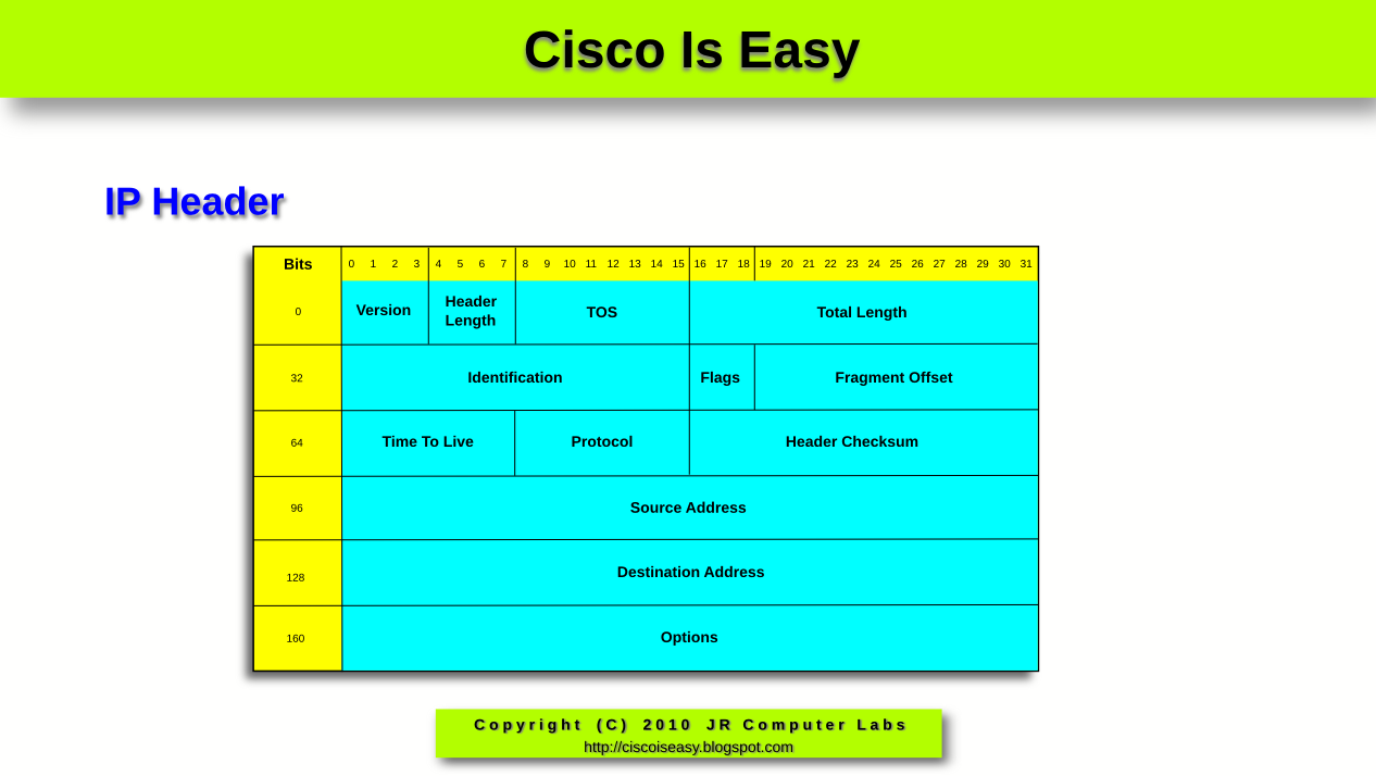
All transmissions use similar process so, as an example, I'm going to show you a typical web client to web server transmission step-by-step. The methodology is almost identical for all other types of data exchange. Before I do that though, please familiarize yourself with the headers that will be used during the encapsulation (sender) and de-encapsulation (receiver) process. Do NOT dwell on those, or try to understand all the mentioned fields. Instead, take a brief look, and refer to them while reading the lesson.

Transport Layer Headers (layer 4)

Pic. 1 - UDP Header (used mostly in voice/video transmissions/dns queries, etc.)


Pic. 2 - TCP Header (used when reliable transport is required)


Internet Layer Header (layer 3)

Pic. 3 - IP Header


Data-Link Layer Header (layer 2)

Pic. 4 Ethernet Header (most commonly used technology in our LAN networks)

Click on the pictures to enlarge them.

NOTICE!
The following discussion has been simplified in order to help you understand the general process. Keep in mind that in reality, it is much more complex process than the explanation presented below.


Web Client to Web Server Transmission Step-by-Step

The best way to learn the theory is to see things working in practice. That is why, I am going to capture the web traffic initiated by my client computer destined to my web server. Before you delve into analyzing the details, please familiarize yourself with my client and server addresses first.

Web Client Details:
IP Address: 192.168.1.13 255.255.255.0
MAC Address: 00:24:e8:fa:07:1a

Web Server Details:
IP Address: 192.168.1.1 255.255.255.0
MAC Address: 00:50:bf:9c:45:6a

Step 1
In the URL field of my web browser I'm typing in the address of the server using HTTP protocol (Layer 5 protocol used as an example). This will tell the application what the address of the server is. I accept it by hitting the 'Enter' key.

Pic. 5 - URL Address of the web server


Step 2
The client computer realizes that the address of the recipient (web server) is in the same layer 3 network (the first 24 bits of the both source and destination address are the same). More on this, you will learn in the upcoming lessons. As a result of that, the client needs to obtain the MAC address of the web server first. Recall from the previous lesson that IP packet is encapsulated in layer 2 header, which in our case uses source and destination MAC addresses. Normally, the client computer is going to check the local 'arp cache' to find out if the mapping of the destination IP address to its MAC address is there. If not, like in my example, the client is going to issue 'ARP Request' message (Address Resolution Protocol) to learn the destination's computer MAC address. This request is propagated to ALL local machines in the network 192.168.1.0/24. Pay attention to the highlighted lines in the picture. The destination MAC address in the query is the Ethernet broadcast address: FF:FF:FF:FF:FF:FF. In the ARP request the client computer asks 192.168.1.1 for its MAC address (which, as of right now, is all 0s; see the below pic. 6).

Pic. 6 - ARP Request


NOTICE!
The ARP request is considered a layer 2 protocol. It is directly encapsulated in the Ethernet II frame. Its header is presented in the second line in the middle panel (under the 'Frame 3').


Step 3
There is only one computer with its unique address of 192.168.1.1 in the network. This one replies to the query with the 'ARP Reply' message back to the sender of the request, telling it what the MAC address it uses. The address is seen in the middle of the pic. 7 (highlighted) belongs to web server. The address reads:
00:50:bf:9c:45:6a

Pic. 7 - ARP Reply


Step 4
The MAC address of the web server was the missing piece of information the client needed to proceed with the TCP session establishment. TCP, being a session-oriented and reliable transport protocol, must establish the mutual communication with the web server first, before it is allowed to send the data from the web browser. This is known as the 3-way handshake. Let us look at the details of the first TCP segment in this session establishment phase.

1. The client (192.168.1.13) sends an 'empty' TCP segment (i.e. with no data from the application included in it).

  • It chooses a random source port number first. In the transmission presented the TCPSrc-Port: 51504 is chosen. Also it uses the Dst-Port: 80 which identifies web server destination application. This pair of ports will uniquely identify this particular transmission, as the client can initiate multiple transmissions at the same time. Those two ports (source and destination port numbers) allow multiple transmissions without a risk of 'mixing up' which reply from the servers should be sent back to which inititiating that request process. This way, the process that initiated transmission is going to receive the right reply. I need to add here that TCP and UDP ports are divided into two major groups: 'well-known ports' which are ports between 1-1023 (always destination ports for the client initiating transmissions), and 'ephemeral ports' between 1024-65535numbers. The latter ones, clients choose randomly to mark the source process for their transmissions.
  • Sequence Number in the segment = 0. If the web server (destination) receives this segment and replies to it, it will put a value of 1 in the Acknowledgment field. That is an indication for the client, that the first segment did arrive successfully at the server.
  • The SYN flag = 1, and all the rest of the flags are set to 0. It means,that this is the first handshake in the exchange. It is the client's request to establish session with the server.
  •  

    NOTICE!
    The layer 4 segment has been encapsulated in the layer 3 header (pic. 8: 'Internet Protocol') and further encapsulated in the Ethernet frame (pic. 8: Ethernet II). The first line in the middle section of the picture, is what is seen on the wire.


    Pic. 8 -  TCP Syn Segment


    2. The next segment captured (pic. 9) comes from the web server and is the reply for the 'SYN' message sent by the web client. Now, please compare both pictures (pic. 8 and pic. 9). Pay attention to the source and the destination TCP port numbers, and the source and destination addresses used in the layer 3 (IP header) and the layer 2 (Ethernet header). Did you notice they are reversed now?

    • TCP port numbers are now reversed (TCP Src-port=80Dst-port=51504) in order to send the reply directly to the port that initiated the request).
    • The server's segment has the Sequence number=0, but the Acknowledgement number=1. It is what we expected. This means that the delivery of the client's first segment was successful).
    • The flag ACK=1, which is the acknowledgement for the SYN flag from the client.
    • The server also wants to synchronize the transmission with the client. That is why it sets its own SYN=1 in this segment.

    Pic. 9 - Server's response SYN, ACK


    3. The client needs to reply to the server's SYN message with its ACK=1 to finalize the session establishment (see the pic. 10). Here's what you find in the third handshake from the web client:

    • Src-port=51504Dst-port=80.
    • Acknowledgement=1, which is to tell the server that its segment sequence=0 has arrived successfuly.
    • Sequence=1, which means that it is the second segment sent to the server. That's what the server expects to receive (in the next reply from the server, it should seeAcknowledgment=2).
    • The flag ACK=1, which is the response to the SYN=1 flag received from the server.
    This way, the 3-way handshake is complete!

    Pic. 10 - Final ACK from the server


    Step 5
    The client has established session with the server, so now it sends the first DATA packet (GET request), asking the server for its main page (look at pic. 11).

    Pic. 11 - Request from the client web browser 


    NOTICE!
    The data from the client (GET) is encapsulated in the layer 4 header, this in turn is encapsulated in the layer 3 header, and the whole thing further encapsulated in the layer 2 header. It is what I described in the lesson 5. See the details in the pic. 11.


    Step 6
    Finally, the reply comes back from the server to the client with the html page (see the pic. 12).

    Pic. 12 - Reply from the web server


    One last thing, I would like to bring up here. Since the appropriate layer understands its header (TCP-talks-to-TCP, IP-talks-to-IP, Ethernet-talks-to-Ethernet), we have two different inter-layer communications taking place:

    1. Vertical communication occurs when the upper layer is sending something to the lower layer and vice versa.
    2. Horizontal (virtual) communication between hosts when the destination host reads the appropriate header encapsulated by the sender. 
    Both are depicted in the picture below:

    Pic. 13 - Horizontal and vertical inter-layer communication.


    The content of this lesson is very simplified, just to get the juices flow. Below I present a short video which walks you through the whole process again. You might find it useful to fully understand the content of this lesson. If you caught the idea, please proceed to the next lesson.