Showing posts with label method. Show all posts

Mar 13, 2013

Lesson 56 - Introduction to IPv6 - Address Structure


After a very short introduction to IPv6 types of addresses and the header presentation, let's dig deeper and find out more about IPv6 addresses.

Hexadecimal Address Notation
I have already mentioned that IPv6 global space begins with 2000::/3. This means that all public IPv6 addresses now use three bits which amount to value 2 in hex.

Look at this notation of global address one more time:

2000::/3
This is a shortcut for:

2001:0000:0000:0000:0000:0000:0000:0000/3

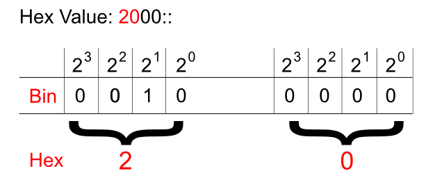
And just like in IPv4 addresses this '/3' tells us to pay attention to the three most significant bits. Hexadecimal to binary conversion is simple. Two digits in hex (for instance: 20) is a one byte value (eight bits). One character stands for four bits (called a nibble). They need to be converted as two separate entities.

Pic. 1 - Hex-to-Binary Conversion.


This way, the hexadecimal 20 becomes 00100000.

In the global IPv6 address scope the first three bits ('/3') will always be set like shown below (as of writing this post):

Pic. 2 - IPv6 Global Address Sequence of Bits.

Okay. What about the hierarchy in IPv6 address?

IPv6 Hierarchy
It is not very different from what we used in IPv4 classes! Do you remember these bits settings in IPv4? If not, look at the below numbers:

Class A - 0xxxxxxx.xxxxxxxx.xxxxxxxx.xxxxxxxx /8
Class B - 10xxxxxx.xxxxxxxx.xxxxxxxx.xxxxxxxx /16
Class C - 110xxxxx.xxxxxxxx.xxxxxxxx.xxxxxxxx /24

The blue color denotes the network portion of the address in these classes. For instance, the '/24' means that 24 most significant bits are the network bits. The remaining ones (eight of them left) are the host bits. This way we create the hierarchy in IPv4 addresses. 


What does it look like in IPv6 then? It is much simpler. See for yourself:

2001:acbd:1234:a1b2:0000:0000:0000:0001/64

The first sixty four bits (blue) are network bits, the remaining ones are the host's interface identifier (host bits). But this, we already know based on the previous post. The network portion is going to be given to us either by the ISP or by the registry (ARIN in the US, RIPE in Europe etc.) if we're a big organization. 

We're told that the length of the prefix assigned to different organizations looks like this:
  • Registries will be assigned /23
  • ISP will be assigned /32
  • Sites will be assigned /48
Say, you are the organization that receives /48 prefix like this:
2001:1234:5678:0000:0000:0000:0000:0000/48.

This gives you two bytes (shown in red) in the network portion to create different networks (red portion: 2^16=65536 different numbers). By the way, get used to the shortcuts:

2001:1234:5678:0000:0000:0000:0000:0000/48 = 2001:1234:5678:0000::/48
IPv6 Interface Identifier (host bits)
How do we get the host portion then? 

In terms of creating the host portion of IPv6 address, if DHCP is not used, we have two options. One way is to do this by hand like presented below (the red color is the interface identifier or the host bits if you will):

2001:1234:5678:1000::1
(abbreviated address which could be expanded to 2001:1234:5678:1000:0000:0000:0000:0001)

But this approach seems somewhat tedious. I mean, who wants to assign addresses on 500 hosts this way?

Another way is to use EUI-64 method which creates the host portion of IPv6 address based on the MAC address of the first Ethernet interface which, at least in theory, should be unique!

Because the MAC address has only 48 bits and not 64, a special procedure has been developed to fill in the gap. Check it out the MAC address of the interface on the router:

Pic. 3 - MAC address of F1/0 Interface.

In the EUI-64 method the operating system takes the MAC address (highlighted) and uses it to create the host bits for the link-local address by default (you can also do this manually). And the same method can be used to assign the host bits in the global address.

Here is the detailed description of how 48 bits of MAC address becomes 64 bit host portion of IPv6 address in EUI-64 method (operating system takes care of these details itself).

Step 1
Flip the 7th bit (counting from left to right) in the MAC address (if it's 1 change it to 0, if it's 0, change it to 1).

In order to do that, operating system must first convert the hexadecimal number of the first byte to the binary form. MAC address used in the example is (as per pic. 3):

CC00.19BA.0010.

(Hex) CC ==> (Bin) 11001100
C=1100

Counting from left to right the 7th bit is: 11001100. This one must be flipped like shown below:
11001110. This gives us the hexadecimal value of: CE.

Step 2
Use the MAC address after modifying the 7th bit in step 1 and inject the FFFE between OUI (first three bytes on the left) and the serial number of the adapter (first three bytes on the right). I will use the colon (:) as the delimiter and blocks of 2-bytes to make it compliant with the IPv6 convention. Look at the result below:

CE00:19FF:FEBA:0010

This way we get 64-bit host portion of the IPv6 address. So my link-local address which uses this method to create the host bits will look like this:

CE00:19FF:FEBA:0010, which is abbreviated to this form:
CE00:19FF:FEBA:10

Step 3
Add the network portion to this construct calculated in step 2. For instance, we know that link-local's network bits are always FF80::/10. So, the whole link-local address is going to be (abbreviated as per Lesson 55's explanation):

FF80::CE00:19FF:FEBA:10
(again, the full 128-bit version is: FF80:0000:0000:0000:E00:19FF:FEBA:0010)

Let's see if this is true when I enable IPv6 support on F1/0 interface. Pay attention to link local address value.

Pic. 4 - IPv6-enabled F1/0 Interface.

Note that just by enabling IPv6 support on the interface IOS automatically creates link-local address using EUI-64, allowing this interface to communicate with hosts residing on this local subnet/network. However, in order to communicate with hosts outside this link-local network, the interface needs a global address as well. This leads us to a correct conclusion that each interface will have two addresses: link-local and global in order to fully operate in IPv6 domain.
IPv6 Global Address Configuration
There are two major methods of configuring IPv6 addresses on our devices:
  • Manual method - You will configure them like we sometimes do with IPv4 right now.
  • Dynamic method - This one offers us IPv6 DHCP servers or the hosts can obtain the network portion of the IPv6 address from their local router (special message is sent called 'Router Solicitation'). In the latter situation the host portion will be generated automatically using the EUI-64 method described above.
Since this post has enough information for one sitting, I'll show you the manual and router solicited methods of configuring IPv6 addresses in my next post. I will also explain what happened to our IPv4 ARP request since broadcast does not exist in IPv6 world anymore!

Mar 12, 2013

Lesson 41 - OSPF Fundamentals Part 4 - Implementation


In this post, I'm going to present the commands and verification steps with regards to OSPF implementation in a single area. Configuration will also include the authentication of OSPF packets.

If you want to go fancy with OSPF the configuration can be quite challenging. Configuring basic OSPF in a single area is very simple though. There are two basic steps required:

  1. Enable OSPF in the 'config' mode.
  2. Instruct the OSPF process which interfaces should be enabled for OSPF and in which areas the links should operate.
Here is the simple topology we are going to use to see the configuration steps.
Pic. 1 -  Topology Diagram.
Icons designed by: Andrzej Szoblik - http://www.newo.pl

OSPF Basic Configuration
The commands which enables OSPF on an interface can look like the below.

Pic. 2 - Example of OSPF Configuration.
router ospf 1 - This command starts the OSPF process 1 on R1.
network 10.1.0.0 0.0.255.2555 area 0 - This statement enables OSPF process on all interfaces which IP addresses are 10.1.x.x (where x.x can be any number as the last two bytes are not checked by the wildcard mask).

What is the wildcard mask in the above statement?

Wildcard mask is an inversed network mask. The bits in the wildcard mask which are set to '0' will check the corresponding bits in the IP address. The bits in the wildcard mask which are set to '1' will ignore the corresponding bits in the IP address.

Pic. 3 - OSPF Wildcard Mask.
Look at the Pic. 2 again. According to the network statement, OSPF will be enabled on F1/0 and S0/1 of R1 (pic. 1).

What network statement could we use in order to enable OSPF on s0/1 interface but not on F1/0?

I can give you a couple of examples. Remember that wildcard mask will use '0s' to check bits in the address and '1s' will ignore them.

Example 1

R1(config)#router ospf 1
R1(config-router)#network 10.1.13.0 0.0.0.255 area 0

This way the wildcard bits are going to check if there are any interfaces which use IP addresses according to 10.1.13.x (where x is any number). These will be OSPF-enabled.

Example 2

R1(config)#router ospf 1
R1(config-router)#network 10.1.13.1 0.0.0.0 area 0

The second example will enable OSPF on the interface that has the EXACT IP address 10.1.13.1. The wildcard bits consists of all '0s' so ALL the corresponding bits in the IP address used must match in order for the interface to be running OSPF protocol.

As you already know, the moment we enable OSPF on an interface, the routing process begins to send the 'hello' packets trying to discover the neighbor(s). If they are discovered the system begins to check parameters in the OSPF header and hello packet. If they agree on the mandatory fields (hello/dead intervale etc.) the are going through several phases to finally synchronize their LSDBs.

Of course, the network statement with wildcard mask does not influence what network mask is going to be advertised along with the IP address. OSPF, being a classless routing protocol, will advertise their networks/subnets as per configuration on the interfaces.

So, let's configure OSPF as per topology diagram (pic. 1) and observe the process of reaching the FULL state (adjacency) using the debug. I will use the most specific wildard mask here but you already know there are a lot of options available to start OSPF on the interfaces.

R1 Configuration:

R1(config)#router ospf 1
R1(config-router)#network 10.1.1.1 0.0.0.0 area 0
R1(config-router)#network 10.1.13.1 0.0.0.0 area 0
R1(config-router)#network 172.16.101.1 0.0.0.0 area 0
R1(config-router)#

R3 Configuration:

R3(config)#router ospf 1
R3(config-router)#network 10.1.3.3 0.0.0.0 area 0
R3(config-router)#network 10.1.13.3 0.0.0.0 area 0
R3(config-rotuer)#network 172.16.103.3 0.0.0.0 area 0
R3(config-router)#

Now, here's the output of the debug statement on R3. Pay attention to the highlighted words and compare them with the OSPF Neighbor State Machine (lesson 38 in the archive of this blog). 

Pic. 4 - Debug IP OSPF Events on R3.
Notice, that it is a point-to-point network, so there is no election of DR and BDR roles.

As part of practical exercise, try to use the same debug in you lab on routers connected using broadcast (Ethernet) links. Watch for DR/BDR election.

OSPF Verification Commands
It is important to be able to perform some basic verification steps. Here are the commands that you will use most often.

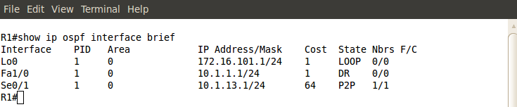
First, let's check if our network statement was correct (OSPF is enabled on the appropriate interfaces).

Pic. 5 - OSPF-enabled Interfaces.

You can also see a detailed output which shows more information with regards to OSPF running on an interface. Check it out.
Pic. 6 - OSPF-enabled Interface Detailed Output (Fa1/0).


Then, I want to make sure that R1 is in FULL state with R3. Here's my command:

Pic. 7 - OSPF Neighbor Check.

Two more commands will be useful as well. First one showing the brief output of LSDB (more detailed output is beyond the scope of this tutorial).

Pic. 8 - OSPF Database.

Notice that both R1 and R3 advertise four links. The loopback0, F1/0, and S0/1 which counts as two links (point-to-point interfaces are advertised as two: the IP address of the next hop and the subnet/network IP).

And finally, the content of OSPF routing table:

Pic. 9 - OSPF Routing Table.

OSPF Authentication
As part of implementation we can authenticate OSPF packets to prevent some rouge routers joining our OSPF domain. If someone configures and plugs in the router, it won't become adjacent with others in the domain unless the right method and password are used.

There are two methods to authenticate OSPF packets:

  1. Simple Password - The password is sent in the clear text format.
  2. MD5 - The password is not sent at all. The digest is created using the shared password between neighbors.
Both methods can be implemented using two different ways.

Let's start with Simple Password method.
Method 1 (password must match on both routers; here: S3cr3t)

R1(config)#router ospf 1
R1(config-router)#area 0 authentication
R1(config-router)#exit
R1(config)#interface serial0/1
R1(config-if)#ip ospf authentication-key S3cr3t

Method 2

R1(config)#interface serial0/1
R1(config-if)#ip ospf authentication
R1(config-if)#ip ospf authentication-key S3cr3t
R1(config-if)#

The first command enables OSPF authentication using Simple Password method (area 0 authentication or ip ospf authentication)

The second command specifies the password that is going to be used (ip ospf authentication-key)

In the first method, OSPF authentication is enabled on ALL interfaces configured to operate in area 0. The second method allows more control as to which interfaces will be sending authenticated OSPF packets.

Pic. 10 - Simple Password Authentication Enabled.

MD5 method can also be configured in two ways.
Method 1 (password must match on both routers; here: S3cr3t)
R1(config)#router ospf 1
R1(config-router)#area 0 authentication message-digest
R1(config-router)#exit
R1(config)#interface serial0/1
R1(config-if)#ip ospf message-digest-key 1 md5 S3cr3t

Method 2

R1(config)#interface serial0/1
R1(config-if)#ip ospf authentication message-digest
R1(config-if)#ip ospf message-digest-key 1 md5 S3cr3t
R1(config-if)#

Both the password (here: S3cr3t) and the key number (here: 1) must match between the neighbors.

Use: show ip ospf int s0/1 to check MD5 authentication.

You might try out the following two commands and see what they show: 

R1#show ip protocols
R1#show ip ospf

The next post is going to be the last one in the OSPF series. We are going to configure OSPF in the more complex topology as well as use some troubleshooting techniques to fix the common configuration issues.

Lesson 24 - Layer 2 Etherchannel


There are two more things I would like to cover in this Cisco fundamentals series that relates to switches: the etherchannel technology and switch port security. Then we move on to layer 3 stuff.

Layer 2 Etherchannel

When you're designing your network one of the factors you always consider is resiliency. Redundant connections are part of a good design. Consider picture 1 below. A rule of thumb says that if all the devices connected to SW3 (access switch on first floor) were transmitting at full speed towards distribution switches (here towards SW1) the traffic is allowed to exceed the capacity of F0/2 port onSW1 20 times. In other words, the link between access layer could oversubscribe 20:1 the link on the distribution switch. Well, it is true in most cases. Remember this is just a rule for an average network.

Pic. 1 - 2-tier network design (access+distribution layer).
Icons designed by: Andrzej Szoblik - http://www.newo.pl

In reality, the situation in which all computers begin to transmit at full speed at the same time never happens. The studies show, that the link between access and distribution switch is utilized in 7% on the average (unless some worm has been planted on your computers). In order to live up to this rule (oversubscription 20:1) you might consider access-to-distribution connection using multiple links that form a virtual connection called: etherchannel. Ports that are members of the etherchannel are represented by a virtual interface called: port-channel.

Etherchannel Advantages
Etherchannel is often used between the switches in order to increase the capacity of the connection between them by performing a load balancing of the frames traversing the channel. Load sharing (balancing) is based either on source or destination MAC address of the transmitting computers when layer 2 etherchannel is used. In case of an active link failure (the port in the channel that transmits the frames), the next link is going to transmit the packets with almost no delay. Keep in mind that the word: etherchannel, is a Cisco term. The industry standard name is link aggregation(IEEE 802.3ad).

Enough of the terminology and reasons for using the technology. Let's get practical.


Cisco offers you three ways of configuring the etherchannel ( three modes of operation):

  1. Dynamic channel negotiation using Link Aggregation Control Protocol (LACP) which is the industry standard implementation.
  2. Dynamic channel negotiation using Port Aggregation Protocol (PAgP) which is Cisco proprietary implementation.
  3. Manual channel configuration without using any form of negotiation.
Etherchannel is a very picky technology. For the channel to be formed correctly (without STP loops etc.), there are a lot of link parameters that must match between switches. Even though I'm not a big fan of "automatic", "I-think-for-you" methods, using either LACP or PAgP seems to be a good idea here. If the channel cannot be formed we have a better reporting as to what went wrong and better protection against the loops that might form between switches on mis-configured channels. But if you use switches from different vendors and dynamic methods fails, even though all parameters, are correct, you can always resort to a manual method.

If I decided to use etherchannel in the topology presented in Pic. 1, I could use the following setup using at least two connections between, each forming a single connection like shown below:

Pic. 2 - Redundant Topology with Etherchannels.
Icons designed by: Andrzej Szoblik - http://www.newo.pl

For the argument sake I will use a simple network topology below (pic. 3). Now, let's see the configuration options.

Pic. 3 - Topology
Icons designed by: Andrzej Szoblik - http://www.newo.pl

Etherchannel using LACP
If you want to configure an etherchannel using a dynamic exchange of packets that is compliant with an industry standard method, the IOS offers you two mode options:

  • active - in this mode the ports are actively sending negotiation frames to the other switch checking if the required parameters match and the channel can be safely formed.
  • passive - in this mode the ports are waiting for the negotiation frames from the other switch in order to form a channel. The ports in the passive mode do NOT initiate any negotiation, but they will reply to negotiation frames received from a neighbor.
In pic. 3, if the parameters between ports F0/13 and F0/14 on SW1 and SW2 are correct (speed, duplex, trunking, vlans allowed etc.), the following channel modes will succeed in forming the etherchannel:
  • SW1 active - SW2 active
  • SW1 active - SW2 passive
  • SW1 passive - SW2 active

NOTICE!
In case, when both use channel mode passive, the etherchannel will not form since no switch is going to start negotiation.

NOTICE!
It is imperative that you check all the settings of the ports first (all ports must have identical configuration). Candidate ports must be in the shutdown mode. This precaution is used to avoid loops and other issues while establishing the etherchannel.


Etherchannel using PAgP
Port Aggregation Protocol is Cisco proprietory protocol helping establish a virtual link between devices using dynamic negotiation (PAgP frames). Similarly to LACP, it has two modes of operation.

  • desirable - in this mode, ports initiate negotiation frames and check if ports on a neighboring switch have proper settings to establish the etherchannel. 
  • auto - in this mode, ports cannot initiate negotiation but will respond to the negotiation frames sent by a neighboring switch.
Similarly, assuming that all the port parameters are identical, the following pairs will work in the topology presented above (pic. 3):
  • SW1 desirable - SW2 desirable
  • SW1 desirable - SW2 auto
  • SW1 auto - SW2 desirable

Etherchannel manual
This mode does not exchange any negotiation frames. Be cautious using this method, as switches won't check if port parameters match. Loops can be formed more easily than with the other two methods.

It's time to get our hands dirty!

The configuration assumes that all port parameters are IDENTICAL!

METHOD 1 - LACP (on both switches in my topology shown in pic. 2)

SW(config)#interface range f0/13 - 14
SW(config-if-range)#channel-group 1 mode active
SW(config-if-range)#end
SW#

Verification (here on SW1):

Pic. 4 -  "show etherchannel summary" command.

Pic. 5 - "show etherchannel 1 detail" command.
In the above picture (pic. 5), part of the output has been truncated for a clarity.

METHOD 2 - PAgP (on both switches in my topology shown in pic. 2)

SW(config)#interface range f0/13 - 14
SW(config-if-range)#channel-group 1 mode desirable
SW(config-if-range)#end
SW#

Verification (here on SW1):

Pic. 6 - "show etherchannel summary" command.


Pic. 7 - "show etherchannel 1 detail" output.
 
In the above picture (pic. 7), part of the output has been truncated for a clarity.


METHOD 3 - Manual (on both switches in my topology shown in pic. 2)

SW(config)#interface range f0/13 - 14
SW(config-if-range)#channel-group 1 mode on
SW(config-if-range)#end
SW#

Verification (here on SW1):

Pic. 8 - "show etherchannel summary" command.


Pic. 9 - "show etherchannel 1 detail" command.
In the above picture (pic. 9), part of the output has been truncated for a clarity.


All configurations that do NOT relate to physical aspects of the ports that are member of the etherchannel must be configured on the port-channel interface now. For instance, if you want to change the channel member ports to a trunk or access mode, the configuration must be done as follows:

SW(config)#interface port-channel 1
SW(config-if)#switchport trunk encapsulation dot1q
SW(config-if)#switchport mode trunk 


I hope this will help you get started. For more information on etherchannel, please refer to Cisco documentation.

In my next post I am going to present switch port security. After that, get ready for layer 3 stuff.