Showing posts with label enable. Show all posts

Mar 13, 2013

Lesson 58 - Introduction to IPv6 - Migration


Now, being equipped with some fundamental IPv6 knowledge, we can try to configure RIPng protocol (RIP Next Generation), as well as try to connect two different IPv6 networks over IPv4 cloud. I'm going to use the same topology in the previous lesson.
Pic. 1 - IPv6-IPv4 Topology Diagram.
Icons designed by: Andrzej Szoblik - http://www.newo.pl

Let's start off with enabling RIPng between R1 and R3 followed by some verification steps. RIPng is very similar to RIPv2 we used before. It uses similar mechanism such as split-horizon, maximum hop-count (16 hops), advertisements every 30 seconds, etc. It uses UDP port 521 (RIP uses UDP port 520).

  
Step 1
Configure IPv6 and IPv4 addresses and enable the interfaces. Check point-to-point reachability.

R1 Configuration:

!
interface Loopback0
 no ip address
 ipv6 address 2001:1:1:1::1/64
!
interface FastEthernet1/0
 no ip address
 duplex auto
 speed auto
 ipv6 address 2001:13:13:13::1/64
!
interface Serial0/0
 ip address 10.1.1.1 255.255.255.252
!

R2 Configuration:

!
interface Loopback0
 no ip address
 ipv6 address 2001:2:2:2::2/64
!
interface FastEthernet1/0
 no ip address
 duplex auto
 speed auto
 ipv6 address 2001:24:24:24::2/64
!
interface Serial0/0
 ip address 10.1.1.2 255.255.255.252
!

R3 Configuration:

!
interface Loopback0
 no ip address
 ipv6 address 2001:3:3:3::3/64
!
interface FastEthernet1/0
 no ip address
 duplex auto
 speed auto
 ipv6 address 2001:13:13:13::3/64
!

R4 Configuration:

!
interface Loopback0
 no ip address
 ipv6 address 2001:4:4:4::4/64
!
interface FastEthernet1/0
 no ip address
 duplex auto
 speed auto
 ipv6 address 2001:24:24:24::4/64
!

Verification:

Pic. 2 - IPv6 Ping Test on R1.

Pic. 2 - IPv6 Ping Test on R2.

Since, pinging by IPv6 address is a bit awkward, you can create name-to-ip mapping using the following commands (here: R1 as an example):

R1 Configuration:

!
R1(config)#ipv6 host R3 2001:13:13:13::3
R1(config)#end
!

Then, you can 'ping R3' (name is case insensitive) instead of using its address.

The routing table of R1 looks like this. You should recognize the addresses easily based on the previous post.

Pic. 4 - R1's IPv6 Routing Table.

Step 2
Enable RIPng to advertise loopbacks. Check the reachability.

In order to support IPv6 routing, you must enable support for it using:
'ipv6 unicast-routing'. Starting RIP process will require to configure a tag for the process (can be number or name). Then, you enable RIPng on the interfaces in question (note: there is no network statement to do that).

R1 Configuration:

!
ipv6 unicast-routing
!
ipv6 router rip TEST
!
interface Loopback0
 no ip address
 ipv6 address 2001:1:1:1::1/64
 ipv6 rip TEST enable
!

interface FastEthernet1/0
 no ip address
 duplex auto
 speed auto
 ipv6 address 2001:13:13:13::1/64
 ipv6 rip TEST enable
!

R2 Configuration:

!
ipv6 unicast-routing
!
ipv6 router rip TEST
!
interface Loopback0
 no ip address
 ipv6 address 2001:2:2:2::2/64
 ipv6 rip TEST enable
!
interface FastEthernet1/0
 no ip address
 duplex auto
 speed auto
 ipv6 address 2001:24:24:24::2/64
 ipv6 rip TEST enable
!

R3 Configuration:

!
ipv6 unicast-routing
!
ipv6 router rip TEST
!
interface Loopback0
 no ip address
 ipv6 address 2001:3:3:3::3/64
 ipv6 rip TEST enable
!
interface FastEthernet1/0
 no ip address
 duplex auto
 speed auto
 ipv6 address 2001:13:13:13::3/64
 ipv6 rip TEST enable
!

R4 Configuration:

!
ipv6 unicast-routing
!
ipv6 router rip TEST
!
interface Loopback0
 no ip address
 ipv6 address 2001:4:4:4::4/64
 ipv6 rip TEST enable
!
interface FastEthernet1/0
 no ip address
 duplex auto
 speed auto
 ipv6 address 2001:24:24:24::4/64
 ipv6 rip TEST enable
!

Verification (here just on R1):

Pic. 5 - R1's RIPng Routing Table.

Note!
R3's Loopback has been advertised to R1. The next-hop-address is the R3's link-local address, NOT the globally unique IPv6 address.

Pic. 6 - Debugging RIPng.

Take time and effort in analyzing the output of the debug. Pay attention to the UDP port number used. It is 521 (RIPv1 and RIPv2 use 520). Also notice that the source IPv6 is the router's link-local address and not globally unique one. Also, the destination address is IPv6 multicast address reserved for RIPng: FF02::9.
Another, worth noting fact is that R3 advertises its loopback (2001:3:3:3::/64) and its locally connected network (2001:13:13:13::/64). 

One more command to check RIPng configuration.

Pic. 7 - IPv6 Protocols.

Step 3
Create tunnel between two IPv6 networks over IPv4 island.

Since CCNA official course does not teach how to create tunnels, I will use 6to4 tunneling method which encapsulates IPv6 packet in IPv4 headers to send them across IPv4 network. These posts do not aspire to help you pass the exam. They are designed as an extra, practical help to master the technologies at the CCNA level instead.

R1 Configuration:

!
interface Tunnel0
 no ip address
 ipv6 address 2001:12:12:12::1/64
 ipv6 rip TEST enable
 tunnel source 10.1.1.1
 tunnel destination 10.1.1.2
 tunnel mode ipv6ip
!

R2 Configuration:

!
interface Tunnel0
 no ip address
 ipv6 address 2001:12:12:12::2/64
 ipv6 rip TEST enable
 tunnel source 10.1.1.2
 tunnel destination 10.1.1.1
 tunnel mode ipv6ip
!

Verification:

Pic. 8 - R3's IPv6 Routing Table.

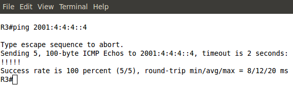
Pic. 9 - Ping Test from R3 to R4.
The Cisco documentation on how to implement IPv6 is available at:
http://www.cisco.com/en/US/docs/ios/ipv6/configuration/guide/12_4/ipv6_12_4_book.html 

If you want to learn more on tunneling methods used during the migration look at:
http://www.cisco.com/en/US/docs/ios/ipv6/configuration/guide/ip6-tunnel.html

Another method called NAT-PT (NAT Protocol Translation) can is explained at:
http://www.cisco.com/en/US/docs/ios/ipv6/configuration/guide/ip6-nat_trnsln_ps6350_TSD_Products_Configuration_Guide_Chapter.html

In my next post, I will address the basics of WAN technologies including some legacy technologies such as Frame-Relay since they are still part of the exam game.

Lesson 45 - EIGRP Fundamentals Part 3 - The Lab


In this post I'll put the pieces together in the practice lab. Our topology will be as presented below:
Pic. 1 - Topology Diagram.
Icons designed by: Andrzej Szoblik - http://www.newo.pl

This post is going to collect bits and pieces from lessons 43 and 44 to show you the implementation on the command line interface with verification steps.

Task List

General requirements

  • All routers must use Autonomous System 1.
  • All networks/subnets must be advertised and reachable.
  • EIGRP authentication should be enabled between R1 and R4.
  1. Enable EIGRP between R1R2 and R3. Make sure loopbacks are advertised. Use the most specific wildcard mask.
  2. Enable EIGRP between R1 and R4. Make sure loopbacks are advertised. Use the most specific wildcard mask on R1. On R4 the network statement should be classful (no wildcard mask).
  3. Enable EIGRP between R2 and R5. Make sure loopbacks are advertised. Use the most specific wildcard mask on R2. On R5 the network statement should be classful (no wildcard mask).
  4. Enable EIGRP authentication between R1 and R4. Use the password 'cisco'.

Lab Solution

Step 1
Enable EIGRP between R1R2 and R3. Make sure loopbacks are advertised. Use the most specific wildcard mask.

Note!
The 'no auto-summary' keyword is not necessary in my topology, but I include it to show you how to disable automatic summarization to the class boundary.
R1 Configuration:

!
R1(config)#router eigrp 1
R1(config-router)#no auto-summary
R1(config-router)#network 172.31.123.1 0.0.0.0
R1(config-router)#network 172.31.1.1 0.0.0.0
R1(config-router)#
!

R2 Configuration:

!
R2(config)#router eigrp 1
R2(config-router)#no auto-summary
R2(config-router)#network 172.31.2.1 0.0.0.0
R2(config-router)#network 172.31.123.2 0.0.0.0
R2(config-router)#
!


Pic. 2 - EIGRP Adjacency Between R1 and R3.


R3 Configuration:

!
R3(config)#router eigrp 1
R3(config-router)#no auto-summary
R3(config-router)#network 172.31.3.1 0.0.0.0
R3(config-router)#network 172.31.3.17 0.0.0.0
R3(config-router)#network 172.31.123.3 0.0.0.0
R3(config-router)#
!

Verification:

Pic. 3 - R3's EIGRP-enabled nterfaces.
Pic. 3 confirms the network statement was correct for each interface.
Pic. 4 - R3's EIGRP Neighbor Table.

Notice!
R3 heard EIGRP hello packets from two neighbors. But to be sure they have exchanged their topology tables, the 'Q Cnt' column must show '0' messages pending (not acknowledged).

Notice!
In the 'output explanation' I show only the most relevant pieces of information. Others are either self-explanatory or not necessary to understand at the CCNA level.

Output Explanation:

  • H - Handle; shows order in which the neighbors were discovered and adjacency built between them.
  • Address - The IP address of the neighbor.
  • Interface - The  local interface where neighbors are discovered.
  • Hold - Length of time in seconds how long the router is going to wait for hello packet before declaring the neighbor down.
  • Uptime - Elapsed time since the local router first heard from the neighbor.
  • SRRT - Smooth Round Trip Timer; amount of time in milliseconds the required to send the packet to the neighbor and receive the acknowledgement.
  • RTO - Retransmit Time Out; amount of time in milliseconds the local router waits before retransmitting EIGRP packet if acknowledgement did not arrive.
  • Q Cnt - The number of EIGRP packets (update, query, reply) that the router keeps in the queue to be sent. Typically, it implies that some EIGRP reliable packets have not been acknowledged.
Pic. 5 - R3's EIGRP Topology Table.

Output Explanation:
  • P - Route is Passive which means that router is not actively looking for a path towards it. It is a required status in stable topology.
  • FD - Feasible Distance (metric value towards the destination)
  • (156160/128256) - The first number (156160) is FD, the second number (128256) is the Advertised Distance advertised by the neighbor (FD of the neighbor). Recall, the Feasibility Condition from the previous lessons.
Pic. 6 - R3's Routing Table.

Output Explanation:
  • D - EIGRP learned prefix; 'show ip route' shows all prefixes including connected networks with explanation of codes.
  • [90/156160] - The first number (90) is the Administrative Distance (trustworthiness) of the protocol, the second number (156160) is the metric based on best FD from the topology table.
  • via 172.31.2.1 - next-hop router (neighbor that advertised it).
  • 00:30:04 - how long ago the prefix was learned.
  • FastEthernet1/0 - The outbound interface towards the destination.
Pic. 7 - R3's EIGRP Details.
Your homework:
look at pic. 7 and consult my previous posts about EIGRP and the topology diagram to understand the highlighted parts.


Step 2
Enable EIGRP between R1 and R4. Make sure loopbacks are advertised. Use the most specific wildcard mask on R1. On R4 the network statement should be classful (no wildcard mask).

R1 Configuration:

!
R1(config-router)#network 172.31.14.1 0.0.0.0
R1(config-router)#
!

R4 Configuration:

!
R4(config)#router eigrp 1
R4(config-router)#no auto-summary
R4(config-router)#network 172.31.0.0
R4(config-router)#network 192.168.4.0
R4(config-router)#
!


Verification should be performed after this step (look at step 1).

Step 3
Enable EIGRP between R2 and R5. Make sure loopbacks are advertised. Use the most specific wildcard mask on R2. On R5 the network statement should be classful (no wildcard mask).

R2 Configuration:

!
R2(config-router)#network 172.31.25.2 0.0.0.0
R2(config-router)#
!


R5 Configuration:

!
R5(config)#router eigrp 1
R5(config-router)#no auto-summary
R5(config-router)#network 192.168.5.0
R5(config-router)#network 172.31.0.0
R5(config-router)#
!

Verification should be performed after this step (look at step 1).

Step 4
Enable EIGRP authentication between R1 and R4. Use the password 'cisco'.

R1 Configuration:

!
R1(config)#key chain MY_EIGRP_KEY
R1(config-keychain)#key 1
R1(config-keychain-key)#key-string cisco
R1(config-keychain-key)#
R1(config-keychain-key)#int s0/2
R1(config-if)#ip authentication key-chain eigrp 1 MY_EIGRP_KEY
R1(config-if)#ip authentication mode eigrp 1 md5
!


R4 Configuration (without prompts):

!
key chain MY_EIGRP_KEY
 key 1
   key-string cisco
!
interface Serial0/2
 ip address 172.31.14.4 255.255.255.0
 ip authentication mode eigrp 1 md5
 ip authentication key-chain eigrp 1 MY_EIGRP_KEY
!

Verification: 
Pic. 8 - R1's Neighbors.

R1 and R4 have re-established neighbor relationships.

In the next post, I'll present a few troubleshooting techniques based on the topology and configuration used in this lesson.

Mar 12, 2013

Lesson 42 - OSPF Fundamentals Part 5 - The Lab


I try to keep these posts as short and informative as possible. Since it takes a moment to do this lab and analyze the results, the troubleshooting section is going to be included in the form of a video presentation at the end of this post (available soon).

Here is our topology. I have removed Frame-Relay links as it goes beyond the scope of this tutorial (some really crazy workbook/journal I started a few days ago might give you an idea about this complexity.

But let's get back to business!

Pic. 1 - OSPF Topology Diagram.
Icons designed by: Andrzej Szoblik - http://www.newo.pl

Since there are five different routers and three types of networks (broadcast, point-to-point and loopback) I will create an action plan and implement it step by step. I'll include some stipulations in order to show you a few things which I might have not talked about yet.
Task List

General Requirements:

  • ALL interfaces should be enabled in area 0. 
  • ALL loopback addresses must be advertises with their configured network mask length (/24) or (/28). 
  1. Enable OSPF in the broadcast network connecting R1R2 and R3. Make sure that R1 is elected the DR and R2 is elected the BDR in the broadcast segment (172.31.123.0/24).
  2. Advertise the loopback subnets on R1R2 and R3. On R3 do NOT use the network statement to advertise the subnet of Loopback1. On R3, while enabling OSPF on Loopback2 using the 'network' statement, use the wildcard bits corresponding to the network mask configured (/28).
  3. Enable OSPF between R1 and R4. Advertise the subnet found on R4's loopback0.
  4. Enable OSPF between R2 and R5. On R5 use only one network statement to enable OSPF on ALL interfaces (also the ones created in the future).
  5. Enable the Simple Password authentication in area 0. Use the password 'cisco'.
Lab Solution

Step 1
Enable OSPF in the broadcast network connecting R1R2 and R3.

Note!
Configuration must be done in this order to ensure R1 is elected the DR, R2 is elected the BDR.

R1 Configuration: 

!
R1#conf t
R1(config)#interface f1/0
R1(config)#ip ospf priority 20
R1(config-if)#router ospf 1
R1(config-router)#router-id 1.1.1.1
R1(config-router)#network 172.31.123.1 0.0.0.0 area 0
R1(config-router)#exit  

R2 Configuration:

!
R2#conf t
R2(config)#interface f1/0
R2(config-if)#ip ospf priority 10
R2(config-if)#router ospf 1
R2(config-router)#router-id 2.2.2.2
R2(config-router)#network 172.31.123.2 0.0.0.0 area 0
R2(config-router)#exit

R3 Configuration:

!
R3#conf t
R3(config)#router ospf 1
R3(config-router)#router-id 3.3.3.3
R3(config-router)#network 172.31.123.3 0.0.0.0 area 0
R3(config-router)#exit


Now, let's give the routers a few seconds to go through the finding neighbors, creating adjacencies. Then a quick verification step shows the following:

Pic. 2 - OSPF Adjacencies.
R3 is adjacent with R1 (DR) and R2 (BDR).

Step 2 
Advertise the loopback subnets on R1R2 and R3. On R3 do NOT use the network statement to advertise the subnet of Loopback1. 

Note!
Loopback interfaces are considered the 'stub' networks by OSPF process and advertised with /32 network mask by default. In order to change it, the 'ip ospf network point-to-point' should be used on loopback interfaces.

Note!
After you have enabled OSPF on the loopbacks, you should check before proceeding to the next router's configuration. Use the following command:
Router#show ip ospf int brief 

R1 Configuration:

!
R1(config)#
R1(config)#interface loopback 1
R1(config-if)#ip ospf network point-to-point
R1(config-if)#router ospf 1
R1(config-router)#network 172.31.1.1 0.0.0.0 area 0
R1(config-router)#exit

R2 Configuration:

!
R2(config)#
R2(config)#interface loopback 1
R2(config-if)#ip ospf network point-to-point
R2(config-if)#router ospf 1
R2(config-router)#network 172.31.2.1 0.0.0.0 area 0
R2(config-router)#exit

Note!
The task stipulates that the subnet of Loopback1 must NOT be advertised like others (no network statement). Also, while enabling OSPF on the Loopback2 use the wildcard mask corresponding to the network mask configured there (/28).

R3 Configuration:

!
R3(config)#
R3(config)#interface loopback 2
R3(config-if)#ip ospf network point-to-point
R3(config-if)#interface loopback 1
R3(config-if)#ip ospf network point-to-point
R3(config-if)#ip ospf 1 area 0
R3(config-if)#router ospf 1
R3(config-router)#network 172.31.3.16 0.0.0.15 area 0
R3(config-router)#

Step 3 
Enable OSPF between R1 and R4. Advertise the subnet found on R4's loopback1.

R1 Configuration:

!
R1(config)#
R1(config)#router ospf 1
R1(config-router)#
R1(config-router)#network 172.31.14.1 0.0.0.0 area 0
R1(config-router)#exit

R4 Configuration:

!
R4(config)#interface loopback1
R4(config-if)#ip ospf network point-to-point
R4(config-if)#router ospf 1
R4(config-router)#router-id 4.4.4.4
R4(config-router)#network 172.31.14.4 0.0.0.0 area 0
R4(config-router)#network 192.168.4.1 0.0.0.0 area 0
R4(config-router)#exit

Step 4
Enable OSPF between R2 and R5. On R5 use only one network statement to enable OSPF on ALL interfaces (also the ones created in the future).

R2 Configuration:

!
R2(config)#
R2(config)#router ospf 1
R2(config-router)#network 172.31.25.2 0.0.0.0 area 0
R2(config-router)#exit

R5 Configuration:

!
R5(config)#interface loopback1
R5(config-if)#ip ospf network point-to-point
R5(config-if)#router ospf 1
R5(config-router)#router-id 5.5.5.5
R5(config-router)#network 0.0.0.0 255.255.255.255 area 0
R5(config-router)#exit

Note! 
Of course, before you proceed to the the final step (OSPF authentication) you should check if all neighbors are adjacent and all routers can reach all the addresses in the network.

Step 5 
Enable the Simple Password authentication in area 0. Use the password 'cisco'.

Note!
This configuration is going to break and re-establish OSPF adjacency.

R1 Configuration:

!
R1(config)#
R1(config)#router ospf 1
R1(config-router)#area 0 authentication
R1(config-router)#int f1/0
R1(config-if)#ip ospf authentication-key cisco
R1(config-if)#int s0/2
R1(config-if)#ip ospf authentication-key cisco

R2 Configuration:

R2(config)#
R2(config)#router ospf 1
R2(config-router)#area 0 authentication
R2(config-router)#int f1/0
R2(config-if)#ip ospf authentication-key cisco
R2(config-if)#int s0/2
R2(config-if)#ip ospf authentication-key cisco

R3 Configuration:

R3(config)#
R3(config)#router ospf 1
R3(config-router)#area 0 authentication
R3(config-router)#int f1/0
R3(config-if)#ip ospf authentication-key cisco

R4 Configuration:

R4(config)#
R4(config)#router ospf 1
R4(config-router)#area 0 authentication
R4(config-router)#int s0/2
R4(config-if)#ip ospf authentication-key cisco

R5 Configuration:

R5(config)#
R5(config)#router ospf 1
R5(config-router)#area 0 authentication
R5(config-router)#int s0/2
R5(config-if)#ip ospf authentication-key cisco

After OSPF authentication has been configured you should check if all the adjacencies have been formed and reachability is restored. If you have a problem with this lab in the troubleshooting sections you will find some tips helping you make this lab work.

Troubleshooting

Troubleshooting short videos available soon.

During the weekend your colleague, who's newly hired junior network administrator, was re-configuring your system. He has accidentally erased all backup configurations and also lost the track of all changes that he introduced. You have been called to help him restore the system.

Initial diagnostics the junior administrator has performed revealed the following problems:

Ticket 1
The subnets: 172.31.3.0/28 and 172.31.3.16/28 are no longer reachable from any other router but R3(loopback1 and loopback2 on R3).

Video Presentation:
http://www.youtube.com/watch?v=vKZASyZbDmE

Ticket 2
R4 lost connectivity to all subnets in the network except for directly connected ones.

Video Presentation:
http://www.youtube.com/watch?v=HEOrvxKmQSU

Ticket 3
R5 lost connectivity to all subnets in the network except for directly connected ones.

Video Presentation:
http://www.youtube.com/watch?v=BlS3Z5kV_Rk

Final Verification
Ping using Tcl script - an elegant way of checking connectivity.

Video Presentation:
http://www.youtube.com/watch?v=VuubpKq0rxg

The next post is going to be an introduction to EIGRP routing protocol.