Showing posts with label network. Show all posts

Mar 13, 2013

The blog's Content list


Disclaimer
The author of the posts will not assume any liability or responsibility to any person or entity with respect to loss or damages incurred from information contained in this blog.


 Quickly navigate to lesson ...
L01 L02 L03 L04 L05 L06 L07 L08 L09 L10
L11 L12 L13 L14 L15 L16 L17 L18 L19 L20
L21 L22 L23 L24 L25 L26 L27 L28 L29 L30
L31 L32 L33 L34 L35 L36 L37 L38 L39 L40
L41 L42 L43 L44 L45 L46 L47 L48 L49 L50
L51 L52 L53 L54 L55 L56 L57 L58

                                  The Blog's Content list

4 - Introduction to TCP/IP Layers
5 - Encapsulation and De-encapsulation Process
6 - Example of TCP/IP Traffic Flow
7 - Building a Home Network
8 - Ethernet and Hub Operations
9 - Bridging/Switching Learning Process
10 - Cisco Discovery Protocol
11 - Layer 2 Connectivity Troubleshooting Part 1
12 - Layer 2 Connectivity Troubleshooting Part 2
13 - Layer 2 Connectivity Troubleshooting Part 3
14 - NTP and Syslog Services
15 - VLANs Overview
16 - VLANs In Practice
17 - Inter VLAN Traffic Flow Analysis
18 - VTP and VLAN Quiz
19 - Spanning-Tree Protocol Overview
20 - Spanning-Tree Protocol Operation
21 - Spanning-Tree Protocol in Practice
22 - Spanning-Tree Cisco Enhancements
23 - Introduction to Rapid STP (802.1w)
24 - Layer 2 Etherchannel
25 - Switch Port Security
26 - Binary World
27 - IPv4 Address Dissected - Part 1
28 - IPv4 Address Dissected - Part 2
29 - IPv4 Subnetting - The Rules
30 - IPv4 Subnetting - Practice
31 - What is a Router ?
32 - Route Selection Process Demystified
33 - Static Routing
34 - Dynamic Routing Protocols Introduction
35 - Routing Information Protocol Part 1
36 - Routing Information Protocol Part 2
37 - Routing Information Protocol Part 3
38 - OSPF Fundamentals Part 1 - Terminology
39 - OSPF Fundamentals Part 2 - Hello Packets
40 - OSPF Fundamentals Part 3 - RouterID and DR/BDR
41 - OSPF Fundamentals Part 4 - Implementation
42 - OSPF Fundamentals Part 5 - The Lab
43 - EIGRP Fundamentals Part 1 - Overview
44 - EIGRP Fundamentals Part 2 - Implementation
45 - EIGRP Fundamentals Part 3 - The Lab
46 - EIGRP Fundamentals Part 4 - Troubleshooting
47 - Packet Filtering with Standard ACL
48 - Standard ACL Examples
49 - Packet Filtering with Extended ACLs
50 - Extended ACL Examples
51 - Network Address Translation Part 1
52 - Network Address Translation Part 2
53 - Network Address Translation Part 3
54 - Network Address Translation Part 4
55 - Introduction to IPv6 - Addresses
56 - Introduction to IPv6 - Address Structure
57 - Introduction to IPv6 - Address Configuration
58 - Introduction to IPv6 - Migration


Lesson 56 - Introduction to IPv6 - Address Structure


After a very short introduction to IPv6 types of addresses and the header presentation, let's dig deeper and find out more about IPv6 addresses.

Hexadecimal Address Notation
I have already mentioned that IPv6 global space begins with 2000::/3. This means that all public IPv6 addresses now use three bits which amount to value 2 in hex.

Look at this notation of global address one more time:

2000::/3
This is a shortcut for:

2001:0000:0000:0000:0000:0000:0000:0000/3

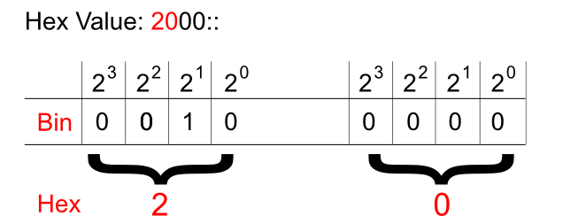
And just like in IPv4 addresses this '/3' tells us to pay attention to the three most significant bits. Hexadecimal to binary conversion is simple. Two digits in hex (for instance: 20) is a one byte value (eight bits). One character stands for four bits (called a nibble). They need to be converted as two separate entities.

Pic. 1 - Hex-to-Binary Conversion.


This way, the hexadecimal 20 becomes 00100000.

In the global IPv6 address scope the first three bits ('/3') will always be set like shown below (as of writing this post):

Pic. 2 - IPv6 Global Address Sequence of Bits.

Okay. What about the hierarchy in IPv6 address?

IPv6 Hierarchy
It is not very different from what we used in IPv4 classes! Do you remember these bits settings in IPv4? If not, look at the below numbers:

Class A - 0xxxxxxx.xxxxxxxx.xxxxxxxx.xxxxxxxx /8
Class B - 10xxxxxx.xxxxxxxx.xxxxxxxx.xxxxxxxx /16
Class C - 110xxxxx.xxxxxxxx.xxxxxxxx.xxxxxxxx /24

The blue color denotes the network portion of the address in these classes. For instance, the '/24' means that 24 most significant bits are the network bits. The remaining ones (eight of them left) are the host bits. This way we create the hierarchy in IPv4 addresses. 


What does it look like in IPv6 then? It is much simpler. See for yourself:

2001:acbd:1234:a1b2:0000:0000:0000:0001/64

The first sixty four bits (blue) are network bits, the remaining ones are the host's interface identifier (host bits). But this, we already know based on the previous post. The network portion is going to be given to us either by the ISP or by the registry (ARIN in the US, RIPE in Europe etc.) if we're a big organization. 

We're told that the length of the prefix assigned to different organizations looks like this:
  • Registries will be assigned /23
  • ISP will be assigned /32
  • Sites will be assigned /48
Say, you are the organization that receives /48 prefix like this:
2001:1234:5678:0000:0000:0000:0000:0000/48.

This gives you two bytes (shown in red) in the network portion to create different networks (red portion: 2^16=65536 different numbers). By the way, get used to the shortcuts:

2001:1234:5678:0000:0000:0000:0000:0000/48 = 2001:1234:5678:0000::/48
IPv6 Interface Identifier (host bits)
How do we get the host portion then? 

In terms of creating the host portion of IPv6 address, if DHCP is not used, we have two options. One way is to do this by hand like presented below (the red color is the interface identifier or the host bits if you will):

2001:1234:5678:1000::1
(abbreviated address which could be expanded to 2001:1234:5678:1000:0000:0000:0000:0001)

But this approach seems somewhat tedious. I mean, who wants to assign addresses on 500 hosts this way?

Another way is to use EUI-64 method which creates the host portion of IPv6 address based on the MAC address of the first Ethernet interface which, at least in theory, should be unique!

Because the MAC address has only 48 bits and not 64, a special procedure has been developed to fill in the gap. Check it out the MAC address of the interface on the router:

Pic. 3 - MAC address of F1/0 Interface.

In the EUI-64 method the operating system takes the MAC address (highlighted) and uses it to create the host bits for the link-local address by default (you can also do this manually). And the same method can be used to assign the host bits in the global address.

Here is the detailed description of how 48 bits of MAC address becomes 64 bit host portion of IPv6 address in EUI-64 method (operating system takes care of these details itself).

Step 1
Flip the 7th bit (counting from left to right) in the MAC address (if it's 1 change it to 0, if it's 0, change it to 1).

In order to do that, operating system must first convert the hexadecimal number of the first byte to the binary form. MAC address used in the example is (as per pic. 3):

CC00.19BA.0010.

(Hex) CC ==> (Bin) 11001100
C=1100

Counting from left to right the 7th bit is: 11001100. This one must be flipped like shown below:
11001110. This gives us the hexadecimal value of: CE.

Step 2
Use the MAC address after modifying the 7th bit in step 1 and inject the FFFE between OUI (first three bytes on the left) and the serial number of the adapter (first three bytes on the right). I will use the colon (:) as the delimiter and blocks of 2-bytes to make it compliant with the IPv6 convention. Look at the result below:

CE00:19FF:FEBA:0010

This way we get 64-bit host portion of the IPv6 address. So my link-local address which uses this method to create the host bits will look like this:

CE00:19FF:FEBA:0010, which is abbreviated to this form:
CE00:19FF:FEBA:10

Step 3
Add the network portion to this construct calculated in step 2. For instance, we know that link-local's network bits are always FF80::/10. So, the whole link-local address is going to be (abbreviated as per Lesson 55's explanation):

FF80::CE00:19FF:FEBA:10
(again, the full 128-bit version is: FF80:0000:0000:0000:E00:19FF:FEBA:0010)

Let's see if this is true when I enable IPv6 support on F1/0 interface. Pay attention to link local address value.

Pic. 4 - IPv6-enabled F1/0 Interface.

Note that just by enabling IPv6 support on the interface IOS automatically creates link-local address using EUI-64, allowing this interface to communicate with hosts residing on this local subnet/network. However, in order to communicate with hosts outside this link-local network, the interface needs a global address as well. This leads us to a correct conclusion that each interface will have two addresses: link-local and global in order to fully operate in IPv6 domain.
IPv6 Global Address Configuration
There are two major methods of configuring IPv6 addresses on our devices:
  • Manual method - You will configure them like we sometimes do with IPv4 right now.
  • Dynamic method - This one offers us IPv6 DHCP servers or the hosts can obtain the network portion of the IPv6 address from their local router (special message is sent called 'Router Solicitation'). In the latter situation the host portion will be generated automatically using the EUI-64 method described above.
Since this post has enough information for one sitting, I'll show you the manual and router solicited methods of configuring IPv6 addresses in my next post. I will also explain what happened to our IPv4 ARP request since broadcast does not exist in IPv6 world anymore!

Lesson 51 - Network Address Translation Part 1


Why NAT?
In 90s we observed an exponential growth of users connecting to a global network called the Internet. As of today, there are billions of people in this global village. The problem is that the designers of TCP/IP protocol suite did not realize this would happen. With the 32 bit IP address that was used originally we could allocate more than 4 billions unique identifiers. Apparently, this is not enough today having billions of devices using public network.

In February 1996 RFC 1918 document has been published. In it, some IP address reservations have been made known as PRIVATE ADDRESS SPACE. The ranges have been reserved as follows:

  • 10.0.0.0 - 10.255.255.255  (10/8 prefix)
  • 172.16.0.0 - 172.31.255.255  (172.16/12 prefix)
  • 192.168.0.0 - 192.168.255.255 (192.168/16 prefix)
Private Address Space is used in our local networks (home, work etc.) and cannot be used as public IP address range. This scope is sometimes referred to as non-routable addresses. This does NOT mean the routers cannot use them to route the packets. It means, that these addresses should never appear as source or destination on the Internet (unless this is some form of attack or misconfiguration).

What is NAT?
Network Address Translation is a technique in which the EDGE router (the one that is connected to ISP (Internet Service Provider) and your LAN, removes the original SOURCE address in the IP header (private range - RFC 1918) and replaces with legitimate, unique, public one leased to us by ISP while sending packets towards the Internet. However it is smart enough to keep this information in the special database called: NAT table. When the reply comes back, the SOURCE and DESTINATION addresses are reversed in the IP header. Once the packet reaches our EDGE router, it uses the right entry in the NAT table to swap the destination IP PUBLIC address (that represented our computer) back to its PRIVATE address.

If it sounds a little vague right now, do not worry since in my next post I will show you this operation step by step using some graphics.

NAT Terminology
If you want to fully understand this technique, you must understand the terminology that is used by it first. The official terms can be found on Cisco web site:
http://www.cisco.com/en/US/tech/tk648/tk361/technologies_tech_note09186a0080094837.shtml

Look at the below picture I'm going to use in the NAT section of this tutorial.

Pic. 1 - NAT Topology
Icons designed by: Andrzej Szoblik - http://www.newo.pl

What you are looking at is two companies (ABC and XYZ) connected to the Internet represented byR3 here. In real life this cloud consists of many routers belonging to different ISPs.

Computers are connected to the LAN and in both cases (I did this on purpose), use the same range of Private Address (192.168.1.0/24). Of course they can use any of addresses listed in RFC 1918.

R1's Serial0/1 interface uses 1.1.13.1, and R2 uses 1.1.12.2 address. Both are NOT described as the PRIVATE so they are PUBLIC or legitimate ones (my apologies if I used somebody's real, public addresses here. They are only used for educational purposes).

Using NAT technique you must be able to properly name them as per Cisco article above. Let's assume that we work for ABC company and we look at all addresses from this standpoint (this is critical). Here's what they are as per Pic. 1:

ABC Company

  • INSIDE LOCAL - address (inside your LAN, before translation). In our example this would be our 192.168.1.0 (ABC) address.
  • INSIDE GLOBAL - address used on the router's interface facing the Internet. GLOBAL means that is is legitimate, globally unique address. These are provided by ISP or Network Information Center (RIPE in Europe, ARIN in the US, etc.). For instance, in the example this would be 1.1.13.1 address.
  • OUTSIDE GLOBAL - address which is also globally unique (like inside global), but is leased to another company, not us (remember? We're ABC here). In this example this would be 1.1.12.2 for instance.
  • OUTSIDE LOCAL - address of the outside host as it appears to our local hosts. Typically in the NAT table we see them as OUTSIDE GLOBAL addresses. Our R1 router will never see XYZ company's 192.168.1.0 scope since it will be translated into a public IP before they send packets towards the Internet.

If you want to read more in-depth description of the terminology please, read the Cisco article I included in this post.

This concludes the introduction to NAT. In my next post, we will inspect step-by-step the process of NAT on the router.

Lesson 44 - EIGRP Fundamentals Part 2 - Implementation


In the previous post (lesson 43) I have laid the foundations related to EIGRP terminology. Without understanding those keywords and their meaning it is hard to implement and analyze the behavior of this routing protocol.

The basic implementation steps, like in case of other routing protocols we have learned so far, requires two major steps:

  1. Enable EIGRP process in the 'config' mode.
  2. Instruct EIGRP which interfaces should participate in the EIGRP domain.
The second step is accomplished with the 'network' statement in the EIGRP routing context. This statement instructs EIGRP routing process which interfaces EIGRP will run on. The consequences of enabling EIGRP on the interface are similar to what we saw in OSPF configuration:
  • EIGRP-enabled interface begins to send EIGRP 'hello' packets in order to discover the neighbors. The address used to advertise these 'hello' packets is well-known, reserved multicast address: 224.0.0.10.
  • EIGRP-enabled interface allow the EIGRP process to read the address and network mask configured on this interface and advertise this network or subnet out other EIGRP-enabled interfaces where the neighbor(s) has/have been discovered and the relationship has been formed with them.
The 'network' statement can take a form of classful (as per IP class A, B, C; without a wildcard mask) or classless (using wildcard mask similar to OSPF) entry.

Also, worth noting here is that the command that starts the EIGRP process is followed by a number which is the Autonomous System number. Unlike OSPF which is the process ID and has local significance, AS number in EIGRP is important as it must match between the neighbors. Example of enabling EIGRP:

router eigrp 1

Number '1' is the Autonomus system number (between 1-65535) which must be the same on all EIGRP speaking routers in the domain.

The following list of parameters must match between EIGRP neighbors in order to successfully establish neighbor relationships: 

  1. Autonomous System number.
  2. K-Values (look at the previous lesson).
  3. If authentication is used both: the key number, the password, and the date/time the password is valid must match.
  4. The neighbors must be on common subnet (all IGPs follow this rule).
Since the 'network' keyword uses either a classful statement or it can take a wildcard mask (inversed mask) as its argument, consider the following four examples which accomplish the SAME goal: all interfaces of R3 are going to be EIGRP-enabled.
Pic. 1 - R3's 
Icons designed by: Andrzej Szoblik - http://www.newo.pl

Example 1

!
router eigrp 1
 network 172.31.0.0
!

Example 2 

!
router eigrp 1
 network 172.31.123.0 0.0.0.255
 network 172.31.3.0 0.0.0.15
 network 172.31.3.16 0.0.0.15
!

Example 3 

!
router eigrp 1
 network 172.31.123.0 0.0.0.255
 network 172.31.3.0 0.0.0.255
!

Example 4 

!
router eigrp 1
 network 172.31.123.3 0.0.0.0
 network 172.31.3.1 0.0.0.0
 network 172.31.3.17 0.0.0.0
!


They all achieve the same result: all interface become EIGRP-enabled.

EIGRP is partially a Distance Vector routing protocol. By default the automatic summarization to the class boundary takes place. The command that disables that behavior is: 'no auto-summary' used under EIGRP process.

EIGRP uses five different types of the packets to communicate. Three of them are reliable and must be acknowledged by the receiver. The EIGRP packets are as follows:

  1. Hello (unreliable).
  2. Updates (reliable).
  3. Queries (reliable).
  4. Replies (reliable).
  5. Acknowledgement (unreliable.

The last point I'd like to make relates to the ability of EIGRP to authenticate its packets. EIGRP currently (as of the time of writing this post) uses only one protocol which is MD5.

If you decide to configure authentication of EIGRP packets there are two major steps you must configure:

  1. Configure a key chain with the parameters such as the password(s) and the date/time they are valid.
  2. Apply authentication method and the key chain on per-interface basis.
Example of key chain configuration on R3 in Autonomous System 1. 
!
! Key Chain Configuration
!
R3(config)#key chain EIGRP
R3(config-keychain)#key 1
R3(config-keychain-key)#key-string S3cr3t!!!
!
! Enabling authentication on F1/0 interface - EIGRP AS 1 here
!
R3(config-if)#ip authentication mode eigrp 1 md5
R3(config-if)#ip authentication key-chain eigrp 1 EIGRP
R3(config-if)#
!

  • 'EIGRP' - The name of the key chain in my configuration. It can be any name.
  • 'key 1' - Number '1' must match be used on the neighbor's interface connected to R3's F1/0 interface.
  • 'S3cr3t!!!' - is the password used as the key 1. Must match between neighbors.
  • mode eigrp 1/ key-chain eigrp 1 - EIGRP AS number configured in the 'config' mode.
There are two other commands available under 'key 1' which I did not used:
  1. Accept-lifetime - date/time in which EIGRP packets signed with the digest based on the key-string will be accepted by the receiving router.
  2. Send-lifetime - date/time in which EIGRP packets will be signed using the key-string specified. The digest will be attached to all EIGRP packet types.
Since I did not use these two options (NTP time synchronization is needed), the key 1, using the password (here: S3cr3t!!!) is valid forever.


In the next post, I'm going to use this lesson's theory and put it into practice.

Mar 12, 2013

Lesson 42 - OSPF Fundamentals Part 5 - The Lab


I try to keep these posts as short and informative as possible. Since it takes a moment to do this lab and analyze the results, the troubleshooting section is going to be included in the form of a video presentation at the end of this post (available soon).

Here is our topology. I have removed Frame-Relay links as it goes beyond the scope of this tutorial (some really crazy workbook/journal I started a few days ago might give you an idea about this complexity.

But let's get back to business!

Pic. 1 - OSPF Topology Diagram.
Icons designed by: Andrzej Szoblik - http://www.newo.pl

Since there are five different routers and three types of networks (broadcast, point-to-point and loopback) I will create an action plan and implement it step by step. I'll include some stipulations in order to show you a few things which I might have not talked about yet.
Task List

General Requirements:

  • ALL interfaces should be enabled in area 0. 
  • ALL loopback addresses must be advertises with their configured network mask length (/24) or (/28). 
  1. Enable OSPF in the broadcast network connecting R1, R2 and R3. Make sure that R1 is elected the DR and R2 is elected the BDR in the broadcast segment (172.31.123.0/24).
  2. Advertise the loopback subnets on R1, R2 and R3. On R3 do NOT use the network statement to advertise the subnet of Loopback1. On R3, while enabling OSPF on Loopback2 using the 'network' statement, use the wildcard bits corresponding to the network mask configured (/28).
  3. Enable OSPF between R1 and R4. Advertise the subnet found on R4's loopback0.
  4. Enable OSPF between R2 and R5. On R5 use only one network statement to enable OSPF on ALL interfaces (also the ones created in the future).
  5. Enable the Simple Password authentication in area 0. Use the password 'cisco'.
Lab Solution

Step 1
Enable OSPF in the broadcast network connecting R1, R2 and R3.

Note!
Configuration must be done in this order to ensure R1 is elected the DR, R2 is elected the BDR.

R1 Configuration: 

!
R1#conf t
R1(config)#interface f1/0
R1(config)#ip ospf priority 20
R1(config-if)#router ospf 1
R1(config-router)#router-id 1.1.1.1
R1(config-router)#network 172.31.123.1 0.0.0.0 area 0
R1(config-router)#exit  

R2 Configuration:

!
R2#conf t
R2(config)#interface f1/0
R2(config-if)#ip ospf priority 10
R2(config-if)#router ospf 1
R2(config-router)#router-id 2.2.2.2
R2(config-router)#network 172.31.123.2 0.0.0.0 area 0
R2(config-router)#exit

R3 Configuration:

!
R3#conf t
R3(config)#router ospf 1
R3(config-router)#router-id 3.3.3.3
R3(config-router)#network 172.31.123.3 0.0.0.0 area 0
R3(config-router)#exit


Now, let's give the routers a few seconds to go through the finding neighbors, creating adjacencies. Then a quick verification step shows the following:

Pic. 2 - OSPF Adjacencies.
R3 is adjacent with R1 (DR) and R2 (BDR).

Step 2 
Advertise the loopback subnets on R1, R2 and R3. On R3 do NOT use the network statement to advertise the subnet of Loopback1. 

Note!
Loopback interfaces are considered the 'stub' networks by OSPF process and advertised with /32 network mask by default. In order to change it, the 'ip ospf network point-to-point' should be used on loopback interfaces.

Note!
After you have enabled OSPF on the loopbacks, you should check before proceeding to the next router's configuration. Use the following command:
Router#show ip ospf int brief 

R1 Configuration:

!
R1(config)#
R1(config)#interface loopback 1
R1(config-if)#ip ospf network point-to-point
R1(config-if)#router ospf 1
R1(config-router)#network 172.31.1.1 0.0.0.0 area 0
R1(config-router)#exit

R2 Configuration:

!
R2(config)#
R2(config)#interface loopback 1
R2(config-if)#ip ospf network point-to-point
R2(config-if)#router ospf 1
R2(config-router)#network 172.31.2.1 0.0.0.0 area 0
R2(config-router)#exit

Note!
The task stipulates that the subnet of Loopback1 must NOT be advertised like others (no network statement). Also, while enabling OSPF on the Loopback2 use the wildcard mask corresponding to the network mask configured there (/28).

R3 Configuration:

!
R3(config)#
R3(config)#interface loopback 2
R3(config-if)#ip ospf network point-to-point
R3(config-if)#interface loopback 1
R3(config-if)#ip ospf network point-to-point
R3(config-if)#ip ospf 1 area 0
R3(config-if)#router ospf 1
R3(config-router)#network 172.31.3.16 0.0.0.15 area 0
R3(config-router)#

Step 3 
Enable OSPF between R1 and R4. Advertise the subnet found on R4's loopback1.

R1 Configuration:

!
R1(config)#
R1(config)#router ospf 1
R1(config-router)#
R1(config-router)#network 172.31.14.1 0.0.0.0 area 0
R1(config-router)#exit

R4 Configuration:

!
R4(config)#interface loopback1
R4(config-if)#ip ospf network point-to-point
R4(config-if)#router ospf 1
R4(config-router)#router-id 4.4.4.4
R4(config-router)#network 172.31.14.4 0.0.0.0 area 0
R4(config-router)#network 192.168.4.1 0.0.0.0 area 0
R4(config-router)#exit

Step 4
Enable OSPF between R2 and R5. On R5 use only one network statement to enable OSPF on ALL interfaces (also the ones created in the future).

R2 Configuration:

!
R2(config)#
R2(config)#router ospf 1
R2(config-router)#network 172.31.25.2 0.0.0.0 area 0
R2(config-router)#exit

R5 Configuration:

!
R5(config)#interface loopback1
R5(config-if)#ip ospf network point-to-point
R5(config-if)#router ospf 1
R5(config-router)#router-id 5.5.5.5
R5(config-router)#network 0.0.0.0 255.255.255.255 area 0
R5(config-router)#exit

Note! 
Of course, before you proceed to the the final step (OSPF authentication) you should check if all neighbors are adjacent and all routers can reach all the addresses in the network.

Step 5 
Enable the Simple Password authentication in area 0. Use the password 'cisco'.

Note!
This configuration is going to break and re-establish OSPF adjacency.

R1 Configuration:

!
R1(config)#
R1(config)#router ospf 1
R1(config-router)#area 0 authentication
R1(config-router)#int f1/0
R1(config-if)#ip ospf authentication-key cisco
R1(config-if)#int s0/2
R1(config-if)#ip ospf authentication-key cisco

R2 Configuration:

R2(config)#
R2(config)#router ospf 1
R2(config-router)#area 0 authentication
R2(config-router)#int f1/0
R2(config-if)#ip ospf authentication-key cisco
R2(config-if)#int s0/2
R2(config-if)#ip ospf authentication-key cisco

R3 Configuration:

R3(config)#
R3(config)#router ospf 1
R3(config-router)#area 0 authentication
R3(config-router)#int f1/0
R3(config-if)#ip ospf authentication-key cisco

R4 Configuration:

R4(config)#
R4(config)#router ospf 1
R4(config-router)#area 0 authentication
R4(config-router)#int s0/2
R4(config-if)#ip ospf authentication-key cisco

R5 Configuration:

R5(config)#
R5(config)#router ospf 1
R5(config-router)#area 0 authentication
R5(config-router)#int s0/2
R5(config-if)#ip ospf authentication-key cisco

After OSPF authentication has been configured you should check if all the adjacencies have been formed and reachability is restored. If you have a problem with this lab in the troubleshooting sections you will find some tips helping you make this lab work.

Troubleshooting

Troubleshooting short videos available soon.

During the weekend your colleague, who's newly hired junior network administrator, was re-configuring your system. He has accidentally erased all backup configurations and also lost the track of all changes that he introduced. You have been called to help him restore the system.

Initial diagnostics the junior administrator has performed revealed the following problems:

Ticket 1
The subnets: 172.31.3.0/28 and 172.31.3.16/28 are no longer reachable from any other router but R3(loopback1 and loopback2 on R3).

Video Presentation:
http://www.youtube.com/watch?v=vKZASyZbDmE

Ticket 2
R4 lost connectivity to all subnets in the network except for directly connected ones.

Video Presentation:
http://www.youtube.com/watch?v=HEOrvxKmQSU

Ticket 3
R5 lost connectivity to all subnets in the network except for directly connected ones.

Video Presentation:
http://www.youtube.com/watch?v=BlS3Z5kV_Rk

Final Verification
Ping using Tcl script - an elegant way of checking connectivity.

Video Presentation:
http://www.youtube.com/watch?v=VuubpKq0rxg

The next post is going to be an introduction to EIGRP routing protocol.

Lesson 40 - OSPF Fundamentals Part3 - RouterID and DR/BDR


There are two more notions I need to touch upon before we implement OSPF in our topology. These are: OSPF Router ID and special roles of the routers which are appointed in Broadcast and NBMA(Non-Broadcast Multiple Access) networks called Designated Router (DR) and Backup Designated Router (BDR). I thought I would do the practical implementation here as well, but I want to keep the post as short as possible.

OSPF routers exchange LSAs by flooding them to all OSPF neighbors. This flooding results in creating the same Link-State Database (LSDB) on all routers in the area. LSDB is a topology database, (kind of a "road map"), shared by all routers in the area. Then, each router runs Dijkstra's SPF algorithm to choose the best path to each destination, placing itself as a the root (starting point). The product of SPF algorithm operation is the routing table. Recall that all OSPF packets are encapsulated in the OSPF header (loot at previous post). So, LSAs are signed with the Router ID when the router originates and floods them.

So what is this Router ID in the OSPF world?

Router ID
Router ID is going to be chosen automatically unless configured manually, using the 'router-idA.B.C.D' command in OSPF configuration context. The A.B.C.D are four bytes just like an IP address representing the router ID. It can be changed at a later stage but this may require the process clearing (once the router had its ID chosen, changing it always requires this command):

R1#clear ip ospf process

Clearing the OSPF process is disruptive since the router will need to re-establish adjacency with its neighbors.

Initially, a router tries to choose its ID based on the following order of operation:

  1. Router chooses numerically the highest IP address off of the loopback interface.
  2. In case there is no loopback interface configured, the router is going to choose numerically the highest IP address off of the physical interface. 
Neither of these interfaces have to be enabled for OSPF.


OSPF DR/BDR 
Another concept that requires some explanation is the election of Designated Router (DR) andBackup Designated Router (BDR) elected on Broadcast and NBMA networks (such as Frame-Relay, ATM, X.25). It is a role that is valid on per link basis (Broadcast and NBMA). This means that a router can be DR on F0/0 interface (segment of the network) but BDR or DRother on F0/1 interface.

As you recall, all routers need to establish adjacency (full state) with their neighbors. Only then, are their LSDBs synchronized. The process of sending updates to a great number of neighbors in Broadcast and NBMA networks would be very inefficient as their number can be significant. The routers would create the number of adjacencies according to the following (full mesh) formula:

Number_of_Adjacencies = n(n-1)/2

where the 'n' stands for the number of routers neighbored. In case an LSU (update) is sent, there would be a number of exchanges occurring between all neighbors according to the following formula:

Number_of_LSA_Exchanges = n raised to the power of 2.

Consider the following picture.

Pic. 1 - Broadcast Network with Four Routers.
Icons designed by: Andrzej Szoblik - http://www.newo.pl

The next picture shows in part the LSU propagation of the same failed network on R3. This is only a partial picture. This would have to be done 16 times.

Pic. 2 - Partial LSU Exchange with 4 Routers.
Icons designed by: Andrzej Szoblik - http://www.newo.pl

This situation would be very chaotic indeed. Instead, the system on Broadcast and NBMA networks elect one representative called Designated Router which is going to be responsible for propagation of all updates on this segment. In case of the failure of DR there is going to be a Backup Designated Router elected to assume the role of DR. These roles are initially based on the highest 'priority number' assigned on the interface. The default number is 1, so in case of a tie, the highest Router ID is becoming DR and the second highest becomes the BDR. If a router's interface is set to the priority value of 0, the router automatically becomes DRother and does not participate in the election process.

NOTICE!
DR is the only router authorized to pass the updates on to other routers on Broadcast and NBMA networks. It must have FULL reachability to other routers on the segment. 


This is the reason, there are two different addresses reserved for OSPF:

  • 224.0.0.5 - All OSPF enabled routers listen to this address.
  • 224.0.0.6 - DR/BDR router listen to this address.
Hello packets are sent to 224.0.0.5 (unless unicast is used i.e. NBMA networks)
Updates are sent 224.0.0.5 except Broadcast and NBMA network which use 224.0.0.6 address instead.

So, in our example (pic 1, and pic.2), if R3 loses its directly connected network, it sends the update towards 224.0.0.6 (to DR/BDR), and DR is sending this back to all other routers using 224.0.0.5 address. R3 is also going to receive it, but it will silently ignore it as it is the same update (sequence number). Consider the below picture.

Pic. 3 - DR/BDR Elected on Broadcast and NBMA Networks.
Icons designed by: Andrzej Szoblik - http://www.newo.pl

This post ends the theory aspects in relation to OSPF in one area as per CCNA requirements.

In the next post, I will finally put this OSPF knowledge into practice. Then, we will troubleshoot OSPF using the tools learned in the next one.