Showing posts with label bit. Show all posts

Mar 13, 2013

Lesson 56 - Introduction to IPv6 - Address Structure


After a very short introduction to IPv6 types of addresses and the header presentation, let's dig deeper and find out more about IPv6 addresses.

Hexadecimal Address Notation
I have already mentioned that IPv6 global space begins with 2000::/3. This means that all public IPv6 addresses now use three bits which amount to value 2 in hex.

Look at this notation of global address one more time:

2000::/3
This is a shortcut for:

2001:0000:0000:0000:0000:0000:0000:0000/3

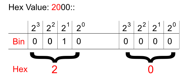
And just like in IPv4 addresses this '/3' tells us to pay attention to the three most significant bits. Hexadecimal to binary conversion is simple. Two digits in hex (for instance: 20) is a one byte value (eight bits). One character stands for four bits (called a nibble). They need to be converted as two separate entities.

Pic. 1 - Hex-to-Binary Conversion.


This way, the hexadecimal 20 becomes 00100000.

In the global IPv6 address scope the first three bits ('/3') will always be set like shown below (as of writing this post):

Pic. 2 - IPv6 Global Address Sequence of Bits.

Okay. What about the hierarchy in IPv6 address?

IPv6 Hierarchy
It is not very different from what we used in IPv4 classes! Do you remember these bits settings in IPv4? If not, look at the below numbers:

Class A - 0xxxxxxx.xxxxxxxx.xxxxxxxx.xxxxxxxx /8
Class B - 10xxxxxx.xxxxxxxx.xxxxxxxx.xxxxxxxx /16
Class C - 110xxxxx.xxxxxxxx.xxxxxxxx.xxxxxxxx /24

The blue color denotes the network portion of the address in these classes. For instance, the '/24' means that 24 most significant bits are the network bits. The remaining ones (eight of them left) are the host bits. This way we create the hierarchy in IPv4 addresses. 


What does it look like in IPv6 then? It is much simpler. See for yourself:

2001:acbd:1234:a1b2:0000:0000:0000:0001/64

The first sixty four bits (blue) are network bits, the remaining ones are the host's interface identifier (host bits). But this, we already know based on the previous post. The network portion is going to be given to us either by the ISP or by the registry (ARIN in the US, RIPE in Europe etc.) if we're a big organization. 

We're told that the length of the prefix assigned to different organizations looks like this:
  • Registries will be assigned /23
  • ISP will be assigned /32
  • Sites will be assigned /48
Say, you are the organization that receives /48 prefix like this:
2001:1234:5678:0000:0000:0000:0000:0000/48.

This gives you two bytes (shown in red) in the network portion to create different networks (red portion: 2^16=65536 different numbers). By the way, get used to the shortcuts:

2001:1234:5678:0000:0000:0000:0000:0000/48 = 2001:1234:5678:0000::/48
IPv6 Interface Identifier (host bits)
How do we get the host portion then? 

In terms of creating the host portion of IPv6 address, if DHCP is not used, we have two options. One way is to do this by hand like presented below (the red color is the interface identifier or the host bits if you will):

2001:1234:5678:1000::1
(abbreviated address which could be expanded to 2001:1234:5678:1000:0000:0000:0000:0001)

But this approach seems somewhat tedious. I mean, who wants to assign addresses on 500 hosts this way?

Another way is to use EUI-64 method which creates the host portion of IPv6 address based on the MAC address of the first Ethernet interface which, at least in theory, should be unique!

Because the MAC address has only 48 bits and not 64, a special procedure has been developed to fill in the gap. Check it out the MAC address of the interface on the router:

Pic. 3 - MAC address of F1/0 Interface.

In the EUI-64 method the operating system takes the MAC address (highlighted) and uses it to create the host bits for the link-local address by default (you can also do this manually). And the same method can be used to assign the host bits in the global address.

Here is the detailed description of how 48 bits of MAC address becomes 64 bit host portion of IPv6 address in EUI-64 method (operating system takes care of these details itself).

Step 1
Flip the 7th bit (counting from left to right) in the MAC address (if it's 1 change it to 0, if it's 0, change it to 1).

In order to do that, operating system must first convert the hexadecimal number of the first byte to the binary form. MAC address used in the example is (as per pic. 3):

CC00.19BA.0010.

(Hex) CC ==> (Bin) 11001100
C=1100

Counting from left to right the 7th bit is: 11001100. This one must be flipped like shown below:
11001110. This gives us the hexadecimal value of: CE.

Step 2
Use the MAC address after modifying the 7th bit in step 1 and inject the FFFE between OUI (first three bytes on the left) and the serial number of the adapter (first three bytes on the right). I will use the colon (:) as the delimiter and blocks of 2-bytes to make it compliant with the IPv6 convention. Look at the result below:

CE00:19FF:FEBA:0010

This way we get 64-bit host portion of the IPv6 address. So my link-local address which uses this method to create the host bits will look like this:

CE00:19FF:FEBA:0010, which is abbreviated to this form:
CE00:19FF:FEBA:10

Step 3
Add the network portion to this construct calculated in step 2. For instance, we know that link-local's network bits are always FF80::/10. So, the whole link-local address is going to be (abbreviated as per Lesson 55's explanation):

FF80::CE00:19FF:FEBA:10
(again, the full 128-bit version is: FF80:0000:0000:0000:E00:19FF:FEBA:0010)

Let's see if this is true when I enable IPv6 support on F1/0 interface. Pay attention to link local address value.

Pic. 4 - IPv6-enabled F1/0 Interface.

Note that just by enabling IPv6 support on the interface IOS automatically creates link-local address using EUI-64, allowing this interface to communicate with hosts residing on this local subnet/network. However, in order to communicate with hosts outside this link-local network, the interface needs a global address as well. This leads us to a correct conclusion that each interface will have two addresses: link-local and global in order to fully operate in IPv6 domain.
IPv6 Global Address Configuration
There are two major methods of configuring IPv6 addresses on our devices:
  • Manual method - You will configure them like we sometimes do with IPv4 right now.
  • Dynamic method - This one offers us IPv6 DHCP servers or the hosts can obtain the network portion of the IPv6 address from their local router (special message is sent called 'Router Solicitation'). In the latter situation the host portion will be generated automatically using the EUI-64 method described above.
Since this post has enough information for one sitting, I'll show you the manual and router solicited methods of configuring IPv6 addresses in my next post. I will also explain what happened to our IPv4 ARP request since broadcast does not exist in IPv6 world anymore!

Mar 12, 2013

Lesson 35 - Routing Information Protocol Part1


Now, that you have learned the principles regarding Distance Vector algorithm, it's time to look at the operation of the oldest distance vector routing protocol: RIP.

Routing Information Protocol is seldom used these days. It has been superseded by more sophisticated protocols (OSPF, EIGRP, IS-IS). However, Cisco still keeps it in the curriculum. All professionals up to the CCIE level (as of writing this post) need to know how it works. In order to enable RIP you must choose which version you want to run. By default, if you configure RIP the version used is version 1. You can change it to version 2 which is more preferred if one want to RIP to begin with. The below table summarizes the main feature of both versions.

Table 1- RIPv1 and RIPv2 Features.

Classful, Classless, and Summarization
Routers share their information (routing table) with their neighbors using advertisements. It is important to know that the shorter the routing table is, the less time a router needs to process the incoming packets in order to find the outbound (egress) interface and expedite them.

If your network design uses proper, consecutive IP scheme, a router can advertise fewer prefixes (routing entries) to their neighbors represented by so called summary routesA summary route represents multiple more specific destinations. But the router which receives this summary route can still send packets towards the subnets that are being summarized. Consider the following picture (pic. 1).

Pic. 1 – Route Summarization.

Icons designed by: Andrzej Szoblik - http://www.newo.pl

In the pic. 1, there are four subnets located behind R1. Router R1 can advertise them ‘as they are’ towards R2. This way, R2 will populate its routing table with all four of them (10.1.0.0/24, 10.1.1.0/24, 10.1.2.0/24, 10.1.3.0/24) with R1 as the gateway to these subnets. However, the subnet addresses behind R1 are designed to be represented by one summary route. This route is going to represent exactly these four subnets. So R1, instead of advertising the four of them, will announce only one address:

10.1.0.0/22

So the question is: how to summarize subnets/networks?

Assuming that IP addresses subnets/networks to be summarized are consecutive numbers when converted to binary, the rule to create the summary route presented in the pic.1 can be applied using three steps.


Step 1
Convert all consecutive summary candidates into binary. List them from the lowest number to the highest like presented in pic.1.

10.1.0.0/24 = 00001010.00000001.00000000.00000000
10.1.1.0/24 = 00001010.00000001.00000001.00000000
10.1.2.0/24 = 00001010.00000001.00000010.00000000
10.1.3.0/24 = 00001010.00000001.00000011.00000000

Step 2
Find the number of bits that is identical and draw the line to see how many bits do not change.

10.1.0.0/24 = 00001010.00000001.00000000.00000000
10.1.1.0/24 = 00001010.00000001.00000001.00000000
10.1.2.0/24 = 00001010.00000001.00000010.00000000
10.1.3.0/24 = 00001010.00000001.00000011.00000000

22 bits do not change = the length of the network mask representing all four entries.

Step 3
Advertise the address with the lowest number in the range using network mask length achieved in the step 2 (bits that never change give you the length of the network mask). The actual commands will be different depending which protocols you use. I will explain them in due time.

10.1.0.0/22 = 00001010.00000001.00000000.00000000
Netmask     = 11111111.11111111.11111100.00000000 = 255.255.252.0

Optionally, you can check if the summary route covers exactly the prefixes. Notice that the two of the bits that change in the third octet will tell you how many addresses have been represented by the summary route (aka aggregate). Look at the bits that do change (in red).

10.1.0.0/24 = 00001010.00000001.00000000.00000000
10.1.1.0/24 = 00001010.00000001.00000001.00000000
10.1.2.0/24 = 00001010.00000001.00000010.00000000
10.1.3.0/24 = 00001010.00000001.00000011.00000000

There are two bits that change in this range in the third byte. This number of bits with the exponent of 2, tells you how many subnets/networks are being summarized. Here: 2 to the power of 2 = 4. Exactly, four subnets have been summarized using prefix 10.1.0.0/22. So this prefix represents exactly the subnets in question.

Now, that you know how to summarize consecutive subnets/networks, let’s see what automatic summarization to the class boundary will look like if you use RIPv1 and have different classes of IP addresses in your desing. Consider the picture presented below (pic. 2).

Pic. 2 – RIPv1 Automatic Summarization to the Class Boundary.

Icons designed by: Andrzej Szoblik - http://www.newo.pl

The routers R1 and R3 are boundary routers between two different classes. They will advertise class A address (10.0.0.0) since RIPv1 does it by default if the outbound interface (the one to send the advertisement) belongs to different class than the subnet being advertised. This will inevitably create confusion as far as R2 is concerned. It will think that both R1 and R3 are gateways to the same class A network 10.0.0.0. As a result of that, the packets destined to the subnets 10.1.1.0 and 10.1.2.0 will not be delivered properly.

In RIPv2 you can disable this automatic summarization by using ‘no auto-summary’ keyword in the ‘config-router’ configuration context. This option makes RIPv2 classless routing protocol (it can advertise subnets of major classes). Classless routing protocols can advertise full prefix (IP address and the network mask) without summarizing it to the class like shown in the pic. 2.

RIPv1 Configuration
In order to configure RIP in our design, we need to perform two steps.

Step 1
Enable RIPv1 protocol process in the global configuration context.

Step 2
Using ‘network’ statement in ‘config-router’ context, instruct the router which interfaces should participate in the RIP process. RIP will run on these interfaces. In RIP protocol the ‘network’ statement has to be followed by the Class A, B, or C address which instructs the router which interfaces should be RIP-enabled.


NOTICE!
The ‘network’ statement is one of the most misinterpreted keywords in Cisco IOS. RIP, OSPF, EIGRP use the ‘network’ statement to inform the router which interfaces should be enabled for the routing protocol. The ‘network’ statement does NOT advertise anything. Only when BGP protocol is used, the ‘network’ statement actually advertises the prefixes since BGP is an application using TCP (port 179) and is not run on the interfaces like all IGP protocols are.


Having said that, let’s enable RIPv1 in my design (pic. 3).

Pic. 3 – Topology Diagram.

Icons designed by: Andrzej Szoblik - http://www.newo.pl

R1 Configuration:

R1#configurer terminal
R1(config)#router rip
R1(config-router)#network 172.31.0.0
R1(config-router)#

R2 Configuration:

R2#configurer terminal
R2(config)#router rip
R2(config-router)#network 172.31.0.0
R2(config-router)#

R3 Configuration:

R3#configurer terminal
R3(config)#router rip
R3(config-router)#network 172.31.0.0
R3(config-router)#

R4 Configuration:

R4#configurer terminal
R4(config)#router rip
R4(config-router)#network 172.31.0.0
R4(config-router)#network 192.168.4.0
R4(config-router)#

R5 Configuration:

R5#configurer terminal
R5(config)#router rip
R5(config-router)#network 172.31.0.0
R5(config-router)#network 192.168.5.0
R5(config-router)#

I suggest that you analyze the topology, configuration and information in this post. There will be few issues we will come across here using RIPv1 (one of them I have not discussed yet but it will rear its ugly head on R3).

I will explain these problems in my next post. I will also show you how to check the configuration of RIP ('show' and 'debug' commands). Also, I will enable RIPv2 to show you the differences in their operation, and how to optimize and verify its operation.

Lesson 32 - Route Selection Process Demistified


It is imperative to know how a router selects the best path to some destination network/subnets if it has more than one to choose from. At least if you are serious about learning the routing principles. In this post I'm going to show you the algorithm a router uses to discriminate between multiple paths to the same destination.

A router can learn the routes to remote networks and subnets using manual instructions or by means of configuring routing protocols. This way routers learn how to reach destination networks/subnets dynamically. This post's primary focus is about Interior Gateway Protocols(IGPs) such as: RIP, OSPF, EIGRP. The only Exterior Gateway Protocol (EGP) we use nowadays is called BGP. It uses a bit more complex decision making process and is beyond the scope of this tutorial. In the future I am going to talk about it in more detail in the workbooks I plan to post in the future.

First things first. There are three terms I need to define in order to explain the process of selecting the best route. These are:

  1. The Longest Match Rule
  2. Administrative Distance
  3. Metric
The Longest Match Rule
In the previous post I showed you an example of routing table with a brief explanation about what each column in the output represented. Pic. 1 is the graphic equivalent of it.

When a router receives a packet, while processing the header, it is the DESTINATION IP address that is compared with the entries in the routing table in order to determine the next step. This next step is to find the egress (outbound) interface and the address of the next device to send the packet to. This form of routing is known as the destination-based routing. The process of comparing the destination IP with the prefixes int the routing table is done bit by bit (yes, routers see IP addresses in the binary notation). The entry that has the longest number of network bits that match the IP destination address is always the best match (best path). This is always the FIRST thing a router checks.

If there is ONLY ONE best match, a router has a simple task to do. It moves the packet to the outbound interface (egress) and encapsulates the packet in the layer 2 header according to the technology/protocol that is used on the outbound interface (Ethernet, PPP, HDCL, Frame-Relay etc.). Then, the frame is converted to bits and placed onto the wire/fiber optic cable.


NOTICE!
If the outbound interface is a multi-access interface (such as Ethernet, Frame-Relay, ATM etc.), the router must know the layer 2 identifier of the next-hop device (layer 3 to layer 2 address resolution). For instance, in case the outbound interface is Ethernet, the MAC address of the next-hop device must be in the router's arp cache (if not found, the arp query is sent). In case, the egress interface is of a point-to-point type (subinterface point-to-point or protocol such as PPP, HDLC etc. is used), there is NO layer 3 to layer 2 resolution being performed. The packet is simply encapsulated in layer 2 frame sent out that interface.


Let's consider the example depicted in pic. 1.

Pic. 1 - The Longest Match Rule.

In this example the router receives an IP packet. The DESTINATION Address in the packet is172.31.1.33. The router is going to compare this address (bit by bit), with the prefixes (address/network-mask) in the routing table presented, trying to find the closest match (the number of bits that are the same). The entry that is the best match will give the router instructions as to what is the address of the next-hop device (here another router) and the outbound interface.

Let's play the router's game and compare all the entries with the DESTINATION IP address of the packet.

There are three candidate entries pointing to three different next-hop routers and three different outbound interfaces (pic. 1). The pic. 2 shows these numbers in the binary notation.

Pic. 2 - Destination IP Address Comparison.

Clearly, when converted into binary, the first entry shows the best match . The number of identical bits between the packet's destination address and router's knowledge about the subnet is 28 identical bits (highlighted in red). The second entry has only 24 identical bits, and the third one, only 16 bits match the destination IP address (class B network address). That is why the egress interface for the packet towards 172.31.1.33 is FastEthernet0/0 (pic. 1).

So far, we have only dealt with the situation in which there is a SINGLE best match. What if there are more than one entries (paths available) in the routing table with the EXACT same longest match?

There are two other parameters a router uses to break the tie:

  1. Administrative Distance
  2. Metric
Administrative Distance
There are the situations that your router(s) may use more than one source of information. Not that you create such situation on purpose. You are better off using one protocol (e.g. OSPF), but reality bites and sometimes you have to support more than one routing protocol in the same routing domain. In such situations your router may receive the same prefix(es) from different sources. As a result of that multiple sources (RIP, OSPF, EIGRP etc.) provider the router with the EXACT same prefix (address/network-mask).

In order to deal with situations like this, Cisco have created a ranking which assign the protocols (sources of information) different levels of "trustworthiness" (if that's a word). This level of "believability" is expressed with the arbitrarily allocated value that is given to different sources of information. This parameter is called: Administrative Distance (or just 'distance'). The LOWER the value of AD is, the more trusted the source of information is going to be.

Consider the pic. 3. The router receives EXACT same prefix (192.168.1.0/24) from two different sources: RIP and OSPF. Since this is going to cause an issue as to which one is better, AD is going to break the tie. OSPF is more trusted than RIP as it has lower value of Administrative Distance assigned to it (110) compared to RIP's (120).

There are many reasons why RIP is less trusted source than OSPF, but explaining it in detail is beyond of the scope of this post. Needless to say, if you do not like Cisco arbitrarily set values, there are ways of changing them. The commands are different for different protocols, and when we get to advanced topics (hopefully), I'm going to show them to you.

Pic. 3 - Advertisement Come from Different Sources (Protocols).

Icons designed by: Andrzej Szoblik - http://www.newo.pl

I have included a few AD values for the most often used protocols to get you going. For more information on that go to Cisco web site. Of course the best way of finding the values is to use my favorite search engine: google ;).

Metric
Another situations that might put a router in a difficult position regarding which path is the best occurs when there are multiple longest match entries in the routing table, coming from the same source. Or more accurately speaking, there are multiple best matches (EXACT prefixes) having the same value of Administrative Distance (AD).

In such situations, the tie-breaker is going to be the LOWEST value of the METRIC.

A metric is the value calculated for each prefix and expresses, for the lack of better word, how far the destination is. The lower the value, the more preferred the path is.

Keep in mind, that the type of metric routing protocols use (the way they calculate it) is different between them and totally INCOMPATIBLE. They use different ways and factors to calculate their metric.

Just to give you a few examples, RIP uses the concept of hop-count. The number (metric) tells the router how many routers the packet must traverse before it reaches the destination.

OSPF on the other hand, uses the cost as its metric. It is calculated based on the bandwidth of the interfaces (links) in the path. This way, its metric is far more sophisticated and more suitable for our networks compared to RIP.

As you see it is not the coincidence that OSPF is more trusted source of information compared to RIP.

Consider the following example (pic. 4).

Pic. 4 - An Example of Metric Types.
Icons designed by: Andrzej Szoblik - http://www.newo.pl

If in your design you decided to use RIP in the above topology, the router A, would choose the best path towards 10.2.2.0/24 through router B. This is because the metric used by RIP takes into consideration the number of routers the packet has to traverse, and nothing else. The path throughrouter B is better (1 hop), as opposed to the path through routers CDB (3 hops). RIP does not factor in the bandwidth of the links in the path.

If you chose to use OSPF instead, the number of hops (routers the packet is going to go through) is irrelevant. OSPF makes forwarding decisions based on the bandwidth available in the paths. This way, OSPF prefers path through routers CDB, rather than through router B (much faster links available).

More on the topic of metrics in the upcoming posts. Now, that you have learned about the factors that help routers determine the best path, you are ready to take a look at the algorithm.

  1. Prefer the path with the longest match entry in the routing table (irrespective of the metric or AD).
  2. In case there are multiple best matches available, check the AD value (if they come from the same source). Choose the source of information with the lowest AD. 
  3. If the best match prefixes (more than one) come from the source with the same AD, choose the lowest metric number.
The same order of operation is presented in the pic. 5.


NOTICE!
When considering Border Gateway Protocol, its metric is very complex (not a single number like all Interior Gateway Protocols tend to use). As a result of that, the rules of finding the best route are also more complex and are beyond the scope of this post.


Pic. 5 - Route Selection Process.

Traffic Sharing
One last scenario. What if a router receives more than one exact longest match prefixes that have the same values of AD and the metric?

All of them are the best candidates and the router performs load sharing (load balancing) using all of the egress interfaces that are the best. Of course, whether it is per-packet, or per flow load-balancing depends on the switching engine configuration of your router.

I hope you have caught the idea by now. Check yourself by answering the following question. You will find the answers for all scenarios presented at the bottom of this post.

Practical Question
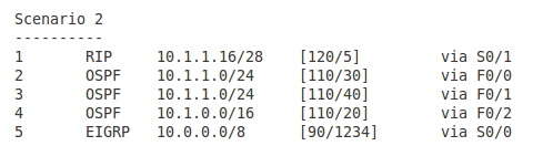
The IP packet has the destination address of 10.1.1.17. The third column on the left is the prefix learned. Which entry in the routing table (number in first column) is going to be the best in the following scenarios? Which outbound interface is going to be used?

Pic. 6 - Scenario 1.

 Pic. 7 - Scenario 2.


Pic. 8 - Scenario 3.
Pic. 9 - Scenario 4
Pic. 10 - Scenario 5

The answers to the question (all scenarios)
Scenario 1
Entry 2 is the correct answer. The egress interface is F0/0.
The router looks for the longest match in the routing table first. Entry 2 learned from RIP has the longest number of bits that are identical with the destination IP (it is the most specific). The remaining sources (OSPF and EIGRP) have fewer bits that match the destination address (they are less specific). The fact that they are more trusted does not apply here since the longest match is always preferred.

Scenario 2
Entry 1 is the correct answer. The egress interface is S0/1.
Just like in the scenario 1, the router looks for a longest match in the routing table first.
Entries 4 and 5 have 8 bits and 16 bits in common with the destination address respectively. Entries 2 and 3 have 24 bits in common. The longest match is the entry 1 having 28 networking bits that are identical with the IP address 10.1.1.17. You can check it by converting the last byte into the binary notation.

Scenario 3
Entry 2 is the correct answer. The egress interface is F0/0.
We can safely rule out the Entries 1 and 4 due to the length of network mask (not the best matches). We're left with Entries 2 and 3. Both have the same number of bits that are identical bits with the destination address (24). Both prefixes come from the same source (OSPF) and as a result of that have the same Administrative Distance value = 120. The tie breaker is going to be the metric value. Entry 2 has a cost of 30 and entry 4 has cost of 40. The lowest is the preferred one.

Scenario 4
Entry 2 is the correct answer. The egress interface is S0/0.
All five entries have the same length of prefix mask, so after longest match rule check we have five candidates.  However, entries 4 and 5 come from OSPF and have higher AD (120) than the first three entries coming from EIGRP routing protocol (90). The lower AD here is preferred. We can rule 4 and 5 out now. Again, all three of them left, have the same AD (90). The tie-breaker is the value of metric again.

Scenario 5
Entries 1 through 3 are the correct answer. The egress interfaces are S0/0, S0/1, and S0/2. The router is going to perform load balancing (traffic sharing).
We can rule out entries 4 and 5 like in the scenario 4. The remaining entries 1 through 3 come from EIGRP (AD=90) and their metrics are the same.

Lesson 30 - IPv4 Subnetting - Practice


In the previous post, I showed you three major rules used in calculating subnets. This knowledge can only be verified in practice though. Let me show you a few examples related to subnet calculations. I hope that looking at this topic from different angles is going to help you understand the concept better and feel confident when planning your IP addressing scheme. The first four questions are merely appetizers for a bigger dish: VLSM.

I am going to refer to my previous post's rules while answering the questions (rule 1, rule 2 and rule 3).

If you still do not remember the weights of all bits, you may consider using this little aid presented below (pic. 1) while calculating subnets, and converting binary network masks into decimal values.

Pic. 1- Subnet Calculation Aid.

This tool is useful before you remember all the weights from left to right and right to left.
Pic. 2 - Example of Subnet Binary-to-Decimal Conversion.

Question 1
Given the prefix 192.168.1.0/24, what should be the length of subnet mask allowing up to 9 subnets?

Answer 1
The address belongs to the class C and uses its default network mask. That leaves us with 8 bits to play with (the last byte). Before we change anything, our address and network mask converted into the binary notation look like shown below (pic. 3).
Pic. 3 - 192.168.1.0/24 in Binary.

In order to create 9 subnets we must extend the existing length of the network mask by 4 bits which allows up to 16 subnets (use calculation aid in pic. 1). If I tried to extend it by 3 bits only, the maximum subnets allowed would be only 8 subnets (rule 2 in lesson 29). So, I must use 4 bits and the result is: 192.168.1.0/28 (192.168.1.0 255.255.255.240).

Pic. 4 - The Answer to Question 1

Question 2
Given the host address 192.168.1.177/29, what are the subnet and broadcast addresses?

Answer 2
In order to determine the subnet and broadcast address of the subnet of this host address, we must look at the length of the network mask first. It is 29 bits (24+5). This tells us that the last byte of the address has 5 bits masked (subnet bits) and 3 bits unmasked (host bits). It is a good idea to look at the the last byte of the address (177) with its network mask using binary notation. Pic. 5 below shows you this clearly.
Pic. 5 - 192.168.1.177/29 in Binary.
Since we must determine the the subnet in which the host resides (177 = 10110001), the host portion of the prefix (host bits reside in the last byte) must all be set to '0'. The byte value with the host zeroed is the address of the subnet (rule 1 pkt.1 in lesson 29). This is the result:

Pic. 6 - Host Bits Zeroed = Subnet Address.

The second part of the question relates to the broadcast address of the subnet. As you remember, in order to obtain the broadcast address, you must put '1' on all host bits of the subnet/network. The subnet has already been determined (pic. 6), so let's put '1' on all bits of the host portion:
.10110111
.10110000 = 176 <- subnet address
..00000111 = 7 <- host bits set to '1'

In decimal it is: 176 + 7 = 183
The broadcast address is: 183.

The below picture illustrates it using binary numbers.

Pic. 7 - Host Bits Set to '1' = Broadcast Address.

Question 3
Given the  prefix 172.16.0.0/17, how many subnets can you create?

Answer3
This is a bit tricky isn't it? In order to answer this question, you don't need any calculator, paper or pen. You must trust the rule 2 in lesson 29. The address and its network mask (called prefix) converted into binary look like presented below:
Pic. 8 - The Number of Subnets for 172.16.0.0/17

As you see the number of bits we have extended the class B address is: 1. So, the number of subnets we can create with it is: 2 subnets, since this subnet bit can be either 1 or 0.
Pic. 9 - Questions 3 Answer

Question 4
What length of network mask would be the most optimal for router's point-to-point connection?

Answer 4
The key to this question is to understand that point-to-point connection needs only 2 host addresses (two points that are connected together). Knowing this, the rest is a piece of cake. We use rule 3 inlesson 29 to determine the length of the network mask that allows 2 host addresses. Check out the picture 10.
Pic. 10 - Calculating Point-to-Point Connection Host Addresses.
If you count ones above the optimal network mask for point-to-point connection is /30. The decimal value is: 255.255.255.252.
Question 5 - Variable Length Subnet Masking (VLSM)
It's time for a big one. Given the topology (pic. 11), calculate IP addresses for each subnet trying to optimize them according the host address requirements. The IP address you should use to create subnets is: 192.168.1.0/24. The number of host addresses in the subnets are as follows:
Subnet 1 = 46 host addresses
Subnet 2 = 16 host addresses
Subnet 3 = 10 host addresses
Subnet 4 = 2 host addresses
Subnet 5 = 2 host addresses

Pic. 11 - VLSM Topology.

Icons designed by: Andrzej Szoblik - http://www.newo.pl

As always, if you know the rules and the method, it is going to be easy thing to do. The rules have been discussed in lesson 29, so let me go about this kind of task now.


NOTICE!
If your design looks similar to mine (optimizing addresses to the number of host required) you muststart the calculation with the largest number of host addresses requirement and work your way down to the least number of host addresses.


This is one of the many methods available. It helps quickly calculate all subnet ranges without using calculator (pen and a piece of paper should do).

Step 1
Determine the length of the network mask for each subnet in question. Keep in mind we focus in on the last byte of IP address 192.168.1.0 (8 bits).
The first three bytes do not change!

Subnet 1 = 46 Host Addresses

In order to allocate 46 addresses we must use 6 host bits. Why? 5 bits will not be enough as 2 raised to the power of 5 is 32. Also, we must decrement two addresses for subnet and broadcast addresses. So using 5 bits would give you only 30 host addresses. Here we go with 6 bits then:

Pic. 12 - Subnet 1 in Binary.
Subnet 2 = 16 Host Addresses

We must repeat the same math for the remaining subnets.  How many host bits to allocate for 16 hosts (subnet 2)? We must use 5 bits. In case we wanted to use only 4 host bits, the maximum number of hosts is 14 (16 - 2).
Pic. 13 - Subnet 2 in Binary

Subnet 3 = 10 Host Addresses

We continue using the same logic.

Pic. 14 - Subnet 3 in Binary.
 Subnet 4 and 5 = 2 Host Addresses Each

On point-to-point links only 2 host addresses area needed. The most optimal network mask is /30(30 bits).

Pic. 15 - Subnet 4 and 5 in Binary.
Step 2
Now, that we know the length of network mask for each subnet, we can start calculating the IP address ranges. 

The subnet 1 address is: 192.168.1.0/26.

The value of the lowest bit in the network mask is going to be our increment used to calculate the next available subnet address. With /26 the increment value is 64 (pic. 16).
So, if we add the increment to the last byte, we get the number of our next available subnet address:
192.168.1.0 + 64 = 192.168.1.64.

From there, this next subnet address (value) - 1 is the broadcast of our current subnet:
192.168.1.64 - 1 = 192.168.1.63 (current broadcast address)
Current subnet value + 1 = the first host address:
192.168.1.0 + 1 = 192.168.1.1 (first host address of current subnet)

Current broadcast address - 1 = the last host's address:
192.168.1.63 - 1 = 192.168.1.62 (last host address of current subnet).

Look at the below pictures which illustrate this method.

Pic. 16 - Subnet 1 - IP addresses


Pic. 17 - Subnet 2 - IP addresses

Pic. 18 - Subnet 3 - IP addresses

 Pic. 19 - Subnet 4 - IP addresses

Pic. 20 - Subnet 5 - IP addresses

Now, we're ready to start talking about routing. In my next post, I will talk about a router, its functions,and  basic operation. From there, we'll start exploring routing protocols.

Lesson 29 - IPv4 Subnetting - The Rules


Now, that we have already learned a few things such as conversions between binary and decimal, how to recognize classes of IP addresses based on the 'first octet rule', and what is the purpose of the network mask, we can tackle IP subnetting.
A natural (default) network mask is used with class C of IP addresses quite often. But it is very uncommon to use class A and class B IP addresses with their natural netmask. They are often sub-netted (broken down into multiple smaller networks). This is accomplished by increasing the length of the default (natural) network mask.


 Incidently, the network IP addresses that use their natural (default) network mask are called                   Classful Networks.


But why do we create subnets to begin with?

There are many reasons why we decide to use subnets rather than classful networks. But the most important is that we want to use IP addresses efficiently since they are a scarce resource these days.

Imagine that you have a huge network to support. It uses class B network address: 172.16.0.0/16. Since the number of bits in the host portion of this address is 16 (the last two bytes are not masked), we can place 65534 hosts in a single network. Even if you used 2000 hosts still it is too much to keep them in one broadcast domain. Can you imagine that many computers sending and receiving broadcasts such as ARP requests? Well, I can imagine that, but it does not mean its efficient. In fact, broadcast traffic would pretty much kill this network. Even with thousand computers that would be way too much broadcast traffic to receive.

If we divide this huge network into multiple subnets with fewer hosts per subnet, we improve the efficiency of the system. A router will connect those subnets to allow unicast communication, but broadcasts will not be propagated between subnets as routers do not forward them. For instance: 172.16.1.0/24 subnet allows only 254 hosts in it. The broadcast will be propagated between this number of hosts rather than among one or two thousands of hosts.

Another reason for using subnets is about relates to public IP addresses that are leased to customers. ISPs do not easily give out whole classes of IP addresses (classful) to companies but rather portions of these (subnets).

Other reasons may be related to security of your hosts. Network divided into chunks with routers as gateways, give you more control as to who can 'talk' to whom.

I use terms such as broadcast or unicast. If you are not sure what these terms mean, let me present brief definitions.

Transmissions:
  • Unicast - a single source host sending to a single destination host.
    Example: Src=192.168.1.1, Dst=192.168.1.2
  • Broadcast - a single source host sending to all hosts in the network/subnet. Example: Src=192.168.1.1, Dst=192.168.1.255 (more on this address later in the post)
  • Multicast - a single host sending to a single group of hosts (IP class D)
    Example: Src=192.168.1.1, Dst=224.10.10.10.
There are three things I would like you to remember before we delve into subnetting.
Rule 1
  1. If the host bits in a given IP address are all set to '0', this is the network or subnet address.
  2. If the host bits in a given IP address are all set to '1', this is the broadcast address (all hosts in the subnet/network are destination).
Rule 2
The formula used to calculate the number of available subnets given the specific length of network mask.

Pic. 1 - Number of Subnet Calculation  - Formula.

Rule 3
The formula used to calculate the number of available hosts per subnet or network given the specific network mask.

Pic. 2 - Number of Hosts Per Network/ Subnet - Formula.

Before we start using the above rules, let me show you a few examples of network, subnet and broadcast addresses based on what we have discussed in the last three posts including this one. If you do not remember the 'first octet rule', which determines the class and the default network mask of an IP address, use the following table as the reference. The number ranges of the first byte determine the classes as shown in pic. 3.

Pic. 3 - Classful Address Table.

Pic. 4 - Network (classful) Addresses and Subnet Addresses (classless).

In order to determine the number of subnet bits to use them as the exponent in the above formula (pic. 1), you must first know what is the default network mask of the IP address according to its class (pic. 3). Then, you must count the bits that were added to this default network mask. These bits allow a number of subnets to be created as per formula in pic. 1. Check out the below example.

Pic. 5 - Number of Subnet Bits (Example).
In the example (pic. 5), IP address belongs to class C since the first byte value is 192 (compare it with pic. 3). Class C uses first three bytes (24 bits) to denote the network portion of the address. Today we can say that its default network mask has the length of 24 bits (255.255.255.0). Since our network mask length is /28, we have extended the default network mask by 4 bits (bits in the green color). Thus, we get 4 subnet bits that must be used in our formula presented in pic. 1.
Pic. 6 - Number of Subnets Available - Calculation.
Using the same example: 192.168.1.0/28, how many host addresses per subnet can we use?

Pic. 5 shows us that with /28 we have 4 bits left for host (total number of bits = 32). In order to calculate the available number of host addresses we must resort to formula presented in pic. 2.

Pic. 7 - Number of Hosts Available - Calculation.
Make sure you understand how the three rules presented here work. In my next post, I'm going to show you how to use them to calculate the subnets based on different criteria such as:

  • Number of subnets per IP address
  • Number of hosts required in the subnet
  • Number of desired host per subnet - Variable Length Subnet Masking (VLSM)