Showing posts with label global. Show all posts

Mar 13, 2013

Lesson 57 - Introduction to IPv6 - Address Configuration


It's time to put our hands to work now. Let's see how we can configure IPv6 addresses. I'm going to use the following topology diagram to present different options with regard to IPv6 address configuration on router's interfaces.
Pic. 1 - IPv6-IPv4 Topology Diagram.
Icons designed by: Andrzej Szoblik - http://www.newo.pl

I will use R1 and R3 to begin with. The whole 'Introduction to IPv6' series will end with connecting these two IPv6 networks over IPv4 cloud to show you one of many migration options available.

As you already know, each IPv6-enabled interface, be it a router or computer's interface, will use two distinct addresses:
  • link-local (FE80::)
  • global (2000::)
Currently there are two global prefixes in use (as of writing this post):
  • 2001 - global addresses
  • 2002 - 6to4 tunnel (without actually creating a tunnel interface).
Let's open R1's console and configure IPv6 address on F1/0 interface. First, I'll use EUI-64 method to derive the host bits based on the MAC address. Take a look:
Pic. 2 - IPv6 Address with EUI-64.

Note, that by just configuring IPv6 on the interface, IPv6 protocol stack gets turned on automatically. You can verify this like shown below:

Pic. 3. IPv6 Address Verification

There area two methods of turning on IPv6 support on an interface in IOS:
  • By using 'ipv6 enable' command.
  • By configuring global IPv6 address.

Both link-local and global addresses are now configured. The subnet is what I typed in, the host portion created based on the MAC address taken from F1/0 interface. Do we always have to use EUI-64? Of course not. Both link-local and global addresses can be created automatically. I have removed the previous configuration (pic. 3) and configured this instead:

Pic. 4 - IPv6 Manual Address Assignment
(link-local and global).

Both addresses (link-local and global) are configured manually. Verify this below now:

Pic. 5 - Verification.

Okay. Let's bring the R1's interface F1/0 up, and jump over to R3 for a moment to configure its F1/0 interface ... differently!

An alternative to the above methods (it is going to be used primarily on the computers rather than routers) is so called 'autoconfig' method. For this method to work you must configure two commands first (as of writing this post in most IOS versions I came across both of these must be turned on):

R1 Configuration: 

R1(config)#ipv6 unicast-routing

R3 Configuration: 

R3(config)#ipv6 unicast-routing
R3(config)#int f1/0
R3(config-if)#ipv6 enable
R3(config-if)#ipv6 address autoconfig

Let's verify configuration of IPv6 with this method!

Pic. 6 - Verification.

The moment I enabled 'ipv6 unicast-routing', the router begins to support this method. R3configured as 'autoconfig' will obtain the network portion of the global address (the most significant 64 bits) from the local router (here: R1) by sending a special message called: Router Solicitation(RS). R1, upon receiving this message is going to reply with Router Advertisement (RA). This way,R3 learns what the network portion of the global address is and using EUI-64 completes the host portion, thus creating full, globally unique address to operate.

In IPv6 world there are no broadcasts, so the neighbor discovery using ARP is no longer working. The neighbor discovery, layer 3 to layer 2 address mapping are done using ICMPv6 protocol. There are four ICMPv6 Neighbor Discovery messages you must be aware of. These are:
  • NS - Neighbor Solicitation, asking for neighbor information.
  • NA - Neighbor Advertisements, introducing yourself to the neighbors.
  • RS - Router Solicitation, asking for info about local routers.
  • RA - Router Advertisements, advertising yourself as an active router.
Let's enable few debugs (remember that these are dangerous commands on production equipment) and see few of these messages being exchanged.

Pic. 7 - Debugging ICMPv6 Communication.

ICMPv6-ND: DAD: FE80::CE02:6FF:FE1E:10 is unique.
The above messages is the Duplicate Address Detection (DAD; mechanism of checking if the link-local is unique).
ICMPv6-ND: Sending NA for FE80::CE02:6FF:FE1E:10 on FastEthernet1/0
IPV6: source FE80::CE02:6FF:FE1E:10 (local)
      dest FF02::1 (FastEthernet1/0)
After checking that R3's link-local address is unique, it introduces itself to all the neighbors on F1/0 interface (Neighbor Advertisement).
ICMPv6-ND: Sending RS on FastEthernet1/0
IPV6: source FE80::CE02:6FF:FE1E:10 (local)
      dest FF02::2 (FastEthernet1/0)
R3 is sending Route Solicitation trying to discover locally active routers in order to obtain the information about the network portion of the global address.
ICMPv6: Received ICMPv6 packet from FE80::1, type 134
ICMPv6-ND: Received RA from FE80::1 on FastEthernet1/0
R3 receives information from R1 (R1's Router Advertisement)
ICMPv6-ND: Sending NS for 2001:13:13:13:CE02:6FF:FE1E:10 on FastEthernet1/0
IPV6: source :: (local)
      dest FF02::1:FF1E:10 (FastEthernet1/0)
R3 is sending the Neighbor Solicitation trying to discover the neighbors. I already knows the 2001:13:13:13::
ICMPv6-ND: Autoconfiguring 2001:13:13:13:CE02:6FF:FE1E:10 on FastEthernet1/0
R3's autoconfiguration is complete.
ICMPv6-ND: DAD: 2001:13:13:13:CE02:6FF:FE1E:10 is unique.
R3's 128-bit global address is unique (Duplicate Address Detection).
ICMPv6-ND: Sending NA for 2001:13:13:13:CE02:6FF:FE1E:10 on FastEthernet1/0
IPV6: source 2001:13:13:13:CE02:6FF:FE1E:10 (local)
      dest FF02::1 (FastEthernet1/0)
      traffic class 224, flow 0x0, len 72+8, prot 58, hops 255, originating
IPv6: Sending on FastEthernet1/0
ICMPv6-ND: Address 2001:13:13:13:CE02:6FF:FE1E:10/64 is up on FastEthernet1/0
R3 is announcing its presence on F1/0 segment (Neighbor Advertisement) and fully configured to operate using IPv6 address.

Note, that the ND (ICMPv6 Neighbor Discovery) communication uses multicast (FF). Two addresses are used here:

FF02::1 - All local hosts on the link.
FF02::2 - All local routers on the link.

One last thought about EUI-64 and link-local address. Since, it is locally significant, this address will be used on ALL interfaces. The reason I mention this is that if you try to check connectivity between link-local interfaces, you must provide the router with the output interface. It uses this address on ALL of them after all. Also, you must type in the full interface name to send icmp echo message using link-local address. Check it out:

Pic. 9 - Ping Connectivity Test.

Let's check R3's neighbors (layer 3 to layer 2 mapping):
Pic. 10 - IPv6 Layer 3 to Layer 2 Mapping.

Yes, this would be your IPv6 equivalent of the 'show arp' command used in IPv4!

In my next post we will configure RIPng (RIP Next Generation) routing protocol. The 'Introduction to IPv6' will finish with a short discussion on IPv4 to IPv6 migration and a quick lab to see how we can route IPv6 packets over IPv4 networks.

Lesson 56 - Introduction to IPv6 - Address Structure


After a very short introduction to IPv6 types of addresses and the header presentation, let's dig deeper and find out more about IPv6 addresses.

Hexadecimal Address Notation
I have already mentioned that IPv6 global space begins with 2000::/3. This means that all public IPv6 addresses now use three bits which amount to value 2 in hex.

Look at this notation of global address one more time:

2000::/3
This is a shortcut for:

2001:0000:0000:0000:0000:0000:0000:0000/3

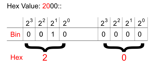
And just like in IPv4 addresses this '/3' tells us to pay attention to the three most significant bits. Hexadecimal to binary conversion is simple. Two digits in hex (for instance: 20) is a one byte value (eight bits). One character stands for four bits (called a nibble). They need to be converted as two separate entities.

Pic. 1 - Hex-to-Binary Conversion.


This way, the hexadecimal 20 becomes 00100000.

In the global IPv6 address scope the first three bits ('/3') will always be set like shown below (as of writing this post):

Pic. 2 - IPv6 Global Address Sequence of Bits.

Okay. What about the hierarchy in IPv6 address?

IPv6 Hierarchy
It is not very different from what we used in IPv4 classes! Do you remember these bits settings in IPv4? If not, look at the below numbers:

Class A - 0xxxxxxx.xxxxxxxx.xxxxxxxx.xxxxxxxx /8
Class B - 10xxxxxx.xxxxxxxx.xxxxxxxx.xxxxxxxx /16
Class C - 110xxxxx.xxxxxxxx.xxxxxxxx.xxxxxxxx /24

The blue color denotes the network portion of the address in these classes. For instance, the '/24' means that 24 most significant bits are the network bits. The remaining ones (eight of them left) are the host bits. This way we create the hierarchy in IPv4 addresses. 


What does it look like in IPv6 then? It is much simpler. See for yourself:

2001:acbd:1234:a1b2:0000:0000:0000:0001/64

The first sixty four bits (blue) are network bits, the remaining ones are the host's interface identifier (host bits). But this, we already know based on the previous post. The network portion is going to be given to us either by the ISP or by the registry (ARIN in the US, RIPE in Europe etc.) if we're a big organization. 

We're told that the length of the prefix assigned to different organizations looks like this:
  • Registries will be assigned /23
  • ISP will be assigned /32
  • Sites will be assigned /48
Say, you are the organization that receives /48 prefix like this:
2001:1234:5678:0000:0000:0000:0000:0000/48.

This gives you two bytes (shown in red) in the network portion to create different networks (red portion: 2^16=65536 different numbers). By the way, get used to the shortcuts:

2001:1234:5678:0000:0000:0000:0000:0000/48 = 2001:1234:5678:0000::/48
IPv6 Interface Identifier (host bits)
How do we get the host portion then? 

In terms of creating the host portion of IPv6 address, if DHCP is not used, we have two options. One way is to do this by hand like presented below (the red color is the interface identifier or the host bits if you will):

2001:1234:5678:1000::1
(abbreviated address which could be expanded to 2001:1234:5678:1000:0000:0000:0000:0001)

But this approach seems somewhat tedious. I mean, who wants to assign addresses on 500 hosts this way?

Another way is to use EUI-64 method which creates the host portion of IPv6 address based on the MAC address of the first Ethernet interface which, at least in theory, should be unique!

Because the MAC address has only 48 bits and not 64, a special procedure has been developed to fill in the gap. Check it out the MAC address of the interface on the router:

Pic. 3 - MAC address of F1/0 Interface.

In the EUI-64 method the operating system takes the MAC address (highlighted) and uses it to create the host bits for the link-local address by default (you can also do this manually). And the same method can be used to assign the host bits in the global address.

Here is the detailed description of how 48 bits of MAC address becomes 64 bit host portion of IPv6 address in EUI-64 method (operating system takes care of these details itself).

Step 1
Flip the 7th bit (counting from left to right) in the MAC address (if it's 1 change it to 0, if it's 0, change it to 1).

In order to do that, operating system must first convert the hexadecimal number of the first byte to the binary form. MAC address used in the example is (as per pic. 3):

CC00.19BA.0010.

(Hex) CC ==> (Bin) 11001100
C=1100

Counting from left to right the 7th bit is: 11001100. This one must be flipped like shown below:
11001110. This gives us the hexadecimal value of: CE.

Step 2
Use the MAC address after modifying the 7th bit in step 1 and inject the FFFE between OUI (first three bytes on the left) and the serial number of the adapter (first three bytes on the right). I will use the colon (:) as the delimiter and blocks of 2-bytes to make it compliant with the IPv6 convention. Look at the result below:

CE00:19FF:FEBA:0010

This way we get 64-bit host portion of the IPv6 address. So my link-local address which uses this method to create the host bits will look like this:

CE00:19FF:FEBA:0010, which is abbreviated to this form:
CE00:19FF:FEBA:10

Step 3
Add the network portion to this construct calculated in step 2. For instance, we know that link-local's network bits are always FF80::/10. So, the whole link-local address is going to be (abbreviated as per Lesson 55's explanation):

FF80::CE00:19FF:FEBA:10
(again, the full 128-bit version is: FF80:0000:0000:0000:E00:19FF:FEBA:0010)

Let's see if this is true when I enable IPv6 support on F1/0 interface. Pay attention to link local address value.

Pic. 4 - IPv6-enabled F1/0 Interface.

Note that just by enabling IPv6 support on the interface IOS automatically creates link-local address using EUI-64, allowing this interface to communicate with hosts residing on this local subnet/network. However, in order to communicate with hosts outside this link-local network, the interface needs a global address as well. This leads us to a correct conclusion that each interface will have two addresses: link-local and global in order to fully operate in IPv6 domain.
IPv6 Global Address Configuration
There are two major methods of configuring IPv6 addresses on our devices:
  • Manual method - You will configure them like we sometimes do with IPv4 right now.
  • Dynamic method - This one offers us IPv6 DHCP servers or the hosts can obtain the network portion of the IPv6 address from their local router (special message is sent called 'Router Solicitation'). In the latter situation the host portion will be generated automatically using the EUI-64 method described above.
Since this post has enough information for one sitting, I'll show you the manual and router solicited methods of configuring IPv6 addresses in my next post. I will also explain what happened to our IPv4 ARP request since broadcast does not exist in IPv6 world anymore!

Lesson 52 - Network Address Translation Part 2


NAT Principles in a Nutshell
Now, that you realize there are not enough addresses for all devices in the global network, we can proceed with the general principles behind NAT.

The idea is quite simple when you think about it. The role of the edge router (the one that connects our private network to ISP) is to replace the original, source address in the IP header (private) with the one that is globally unique.

When the packet comes back, the edge router must have enough information to replace the globally unique address used (which now is the destination address) with the same one that was used by the sender originally (private).

NAT Principles - Detailed Explanation
Using our proper terminology, when the IP packet enters the router's inside interface (connected to the LAN), and is sent out the outside interface (connected to the Internet), it removes the inside local address (private, e.g. 192.168.1.1), makes a note what it did in the so called NAT table, and inserts the inside global address (public) in the IP header instead.

So for instance, the original source 192.168.1.1 becomes 86.46.1.10 when the packet is sent towards the Internet (apologies if I use somebody's real IP address here) .

Then, when the destination host sends the reply back to the original sender, this 86.46.1.10 (former source) becomes the destination address. Our edge router receives it on its 'outside interface'. Since, the outbound interface is now our 'inside interface' the router will need to find the appropriate entry in the NAT table which will allow it to identify the original sender's address (our 192.168.1.1). Its address will be now inserted in the destination field of IP header so the packet will be sent to the appropriate host originating this transmission. Check the step-by-step procedure below to see that more clearly.

Step 1
PC (Src=192.168.1.1) is sending packet towards Cisco web server (Dst=72.163.4.161). Since, the destination is not on the same network, the packet is sent towards the default gateway (MAC address of the router's F0/0). If you have problems with this, try to look back at the lessons about TCP/IP traffic flow.

Step 2
The router R1 receives the frame, checks the MAC address and realizes it is the destination for this Layer 2 frame (its MAC address shows in the destination field of the Ethernet header). Layer 2 frame is stripped off and the IP header is read. The destination IP (72.163.4.161) is not listed in the routing table, but the router has a default route (0.0.0.0/0) which tells it to send it to the ISP's router (here:R2). The packet is moved to the outbound interface (S1/0).

Now comes the tricky part. Both interfaces have been assigned special roles in NAT configuration. The interface F0/0 is configured as 'nat inside' which tells the router that packets sourced here belong to the 'inside local' group of addresses (candidates for translation). And the S1/0 interface is configured as 'nat outside'. This interface cannot send packets out with their original 'inside local' numbers (private addresses defined in RFC 1918). The router must perform the translation (address replacement) as per Step 3.

Step 3
R1 is removing 192.168.1.1 address from the IP header (source), and inserts 'inside global' address given to us by our ISP (for example: 86.46.1.10). You're probably waving your hands right now in protest saying: but my ISP does not give me many addresses. Stick with me for now, I will address this issue in my next post. For now, let's just assume that our ISP is generous and gives us a whole bunch of public IP addresses.

After removing 192.168.1.1 and replacing it with 86.46.1.10, the packet is sent out towards its destination (72.163.4.161). R1 creates a special entry in the NAT Table which will allow it to replace it back to 192.168.1.1 when the packet is sent back from www.cisco.com (72.163.4.161). Look at this action below:

Pic. 1 - Inside Local Address Replaced with Inside Global.
Icons designed by: Andrzej Szoblik - http://www.newo.pl

Step 4
The Cisco web server (72.163.4.161) is replying back to the sender. So, the IP header has the following addresses:
Src = 72.163.4.161
Dst = 86.46.1.10

The routers on the Internet send it back to our ISP (don't ask how it's done), which in turn, sends this towards S1/0 interface. At this stage, tTake this action for granted. The packet arrives on the 'nat outside' interface of R1 (S1/0). This is where the router is going to look into the NAT table, that should have the proper entry created before, allowing it to remove 86.46.1.10 and inserting the previously used address (192.168.1.1). This action allows to send this packet out its 'nat inside' interface (F0/0) back to the host which originated this transmission and expects to receive the reply.

After translation, the header looks as follows:
Src = 72.163.4.161
Dst = 192.168.1.1

The PC receives the reply packet from 72.168.4.161 as expected.

Pic. 2 - Inside Global Replaced with Inside Local.
Icons designed by: Andrzej Szoblik - http://www.newo.pl

If you have many public addresses (inside global) you can configure this type of translation using two methods:

  • Static Translation - one-to-one translation (one inside local is represented by the same inside global address). This allows 24/7 access to that computer (e.g. www, ftp, smtp, etc.) since the entry never ages out.
  • Dynamic Translation - computers can use the public addresses from the pool of available ones. Then, after the transmission ends and the entry ages out, this public (inside global) address is sent back to the pool and other computer can use it. There is not permanent one-to-one translation using this method.
The problem is that in 99.999% cases, ISP only gives you a one public address which is applied on the router's interface facing the Internet ('nat outside'). How does NAT handles this problem?

In such situations we use Port Address Translation (Cisco also calls this method NAT overload). This method I leave for my next post.

Lesson 51 - Network Address Translation Part 1


Why NAT?
In 90s we observed an exponential growth of users connecting to a global network called the Internet. As of today, there are billions of people in this global village. The problem is that the designers of TCP/IP protocol suite did not realize this would happen. With the 32 bit IP address that was used originally we could allocate more than 4 billions unique identifiers. Apparently, this is not enough today having billions of devices using public network.

In February 1996 RFC 1918 document has been published. In it, some IP address reservations have been made known as PRIVATE ADDRESS SPACE. The ranges have been reserved as follows:

  • 10.0.0.0 - 10.255.255.255  (10/8 prefix)
  • 172.16.0.0 - 172.31.255.255  (172.16/12 prefix)
  • 192.168.0.0 - 192.168.255.255 (192.168/16 prefix)
Private Address Space is used in our local networks (home, work etc.) and cannot be used as public IP address range. This scope is sometimes referred to as non-routable addresses. This does NOT mean the routers cannot use them to route the packets. It means, that these addresses should never appear as source or destination on the Internet (unless this is some form of attack or misconfiguration).

What is NAT?
Network Address Translation is a technique in which the EDGE router (the one that is connected to ISP (Internet Service Provider) and your LAN, removes the original SOURCE address in the IP header (private range - RFC 1918) and replaces with legitimate, unique, public one leased to us by ISP while sending packets towards the Internet. However it is smart enough to keep this information in the special database called: NAT table. When the reply comes back, the SOURCE and DESTINATION addresses are reversed in the IP header. Once the packet reaches our EDGE router, it uses the right entry in the NAT table to swap the destination IP PUBLIC address (that represented our computer) back to its PRIVATE address.

If it sounds a little vague right now, do not worry since in my next post I will show you this operation step by step using some graphics.

NAT Terminology
If you want to fully understand this technique, you must understand the terminology that is used by it first. The official terms can be found on Cisco web site:
http://www.cisco.com/en/US/tech/tk648/tk361/technologies_tech_note09186a0080094837.shtml

Look at the below picture I'm going to use in the NAT section of this tutorial.

Pic. 1 - NAT Topology
Icons designed by: Andrzej Szoblik - http://www.newo.pl

What you are looking at is two companies (ABC and XYZ) connected to the Internet represented byR3 here. In real life this cloud consists of many routers belonging to different ISPs.

Computers are connected to the LAN and in both cases (I did this on purpose), use the same range of Private Address (192.168.1.0/24). Of course they can use any of addresses listed in RFC 1918.

R1's Serial0/1 interface uses 1.1.13.1, and R2 uses 1.1.12.2 address. Both are NOT described as the PRIVATE so they are PUBLIC or legitimate ones (my apologies if I used somebody's real, public addresses here. They are only used for educational purposes).

Using NAT technique you must be able to properly name them as per Cisco article above. Let's assume that we work for ABC company and we look at all addresses from this standpoint (this is critical). Here's what they are as per Pic. 1:

ABC Company

  • INSIDE LOCAL - address (inside your LAN, before translation). In our example this would be our 192.168.1.0 (ABC) address.
  • INSIDE GLOBAL - address used on the router's interface facing the Internet. GLOBAL means that is is legitimate, globally unique address. These are provided by ISP or Network Information Center (RIPE in Europe, ARIN in the US, etc.). For instance, in the example this would be 1.1.13.1 address.
  • OUTSIDE GLOBAL - address which is also globally unique (like inside global), but is leased to another company, not us (remember? We're ABC here). In this example this would be 1.1.12.2 for instance.
  • OUTSIDE LOCAL - address of the outside host as it appears to our local hosts. Typically in the NAT table we see them as OUTSIDE GLOBAL addresses. Our R1 router will never see XYZ company's 192.168.1.0 scope since it will be translated into a public IP before they send packets towards the Internet.

If you want to read more in-depth description of the terminology please, read the Cisco article I included in this post.

This concludes the introduction to NAT. In my next post, we will inspect step-by-step the process of NAT on the router.