Showing posts with label request. Show all posts

Mar 11, 2013

Lesson 13 - Layer 2 Connectivity Troubleshooting Part 3


This lesson is the last one in the series on how to troubleshoot connectivity issues at the layer 2 of OSI model. Bear in mind, that these do not involve layer 2 technologies such as VLANs or Spanning-Tree Protocol, since we have not talked about those yet.

NOTICE
The steps presented in this lesson are not the ALL possible diagnostics you can do. And they do not have to be done in this specific order. I am merely listing some logical steps which might be useful in order to 'nail down' the root cause of the problem.


Trouble Ticket 3
New installation as per Pic. 1 shows lack of connectivity between the two computers. Initial diagnostics performed revealed the following facts:

  • Switches are connected via fibre optics cable and the ports show proper status (interface is up, line protocol is up).
  • Computers have proper addresses and subnet masks assigned.
  • Cables connecting computers with switches have been tested and proved to be working correctly.
  • Computers reply to echo requests packets (firewalls disabled).
The technician who set up this new network calls you for help.
Pic. 1 - New design with connectivity problem
Icons designed by: Andrzej Szoblik - http://www.newo.pl

Dealing with this trouble ticket we are going to collect the tools we used in the previous lessons trying to resolve this issue.

Step 1
First let's try to 'divide and conquer' (concept mentioned in lesson 11) by sending ping packets fromPC1 to PC2. Before we do that though, we need to purge the existing ARP cache on PC1 and PC2to have a fresh information. We do that by opening Command Line Interface window and typing: arp -d host-address (linux), or arp -d (MS Windows).
Test results:
  • The pings timed out. No reply from PC2.
Step 2
Since the ARP cache entries age out relatively quickly (depending on which operating system you use), we need to quickly check what they contain Alternatively we can send large series of ping packets.
Test results:
  • PC1 does NOT contain expected mac-to-ip mapping. We expected to see
    192.168.1.2 at 00:1e:4f:b0:b2:fc. It is not there, though.
  • PC2 DOES contain the the right mac-to-ip mapping. It shows the following:
    192.168.1.1 at 00:50:bf:9c:45:6a
    .
These are very interesting results, don't you think? Before we take the next step let's gather what we know so far.

Since the ping was initiated by PC1, it sent its ARP request broadcast message and that query must have been delivered to PC2. We can conclude that, based on the fact that we have clearedPC2's ARP cache in step 1, and it has the proper mapping now. PC2 did receive ARP request fromPC1 and learned what MAC and IP address it uses. 

Step 3
We could omit that step, but we're curious if PC2 replies to the ARP request from PC1. We launch our 'wireshark' tool on PC2, ping again from PC1 to PC2 and capture all packets on PC2. What we discover in this packet trace is that PC2 has replied to ARP request with proper ARP reply unicast message back to PC1.

Step 4
Clearly, something between the computers (switches) does not work properly. It seems that we have some sort of unidirectional communication. What we need to establish is, where this unidirectional communication is taking place. We login to the SW1 and SW2 and issue the following commands ('x' here stands for switch number in Pic. 1):

SWx#show mac address-table interface f0/1
SWx#show mac address-table interface f0/24

Test results:
  • SW1 learns source MAC address of PC1 (00:50:bf:9c:45:6a) on its Fa0/1 interface. This is expected.
  • SW1 does NOT learn MAC address of PC2 (00:1e:4f:b0:b2:fc) on its Fa0/24 interface. This is unexpected. It should learn it from the ARP reply sent by PC2.
  • SW2 learns source MAC address of PC2 (00:1e:4f:b0:b2:fc) on its Fa0/1 interface. This is expected.
  • SW2 learns source MAC address of PC1 (00:50:bf:9c:45:6a) on its Fa0/24 interface. This is expected.
This way, we have discovered that SW1 has unidirectional link towards SW2 (SW2 sends frames towards SW1 but the latter does not seem to receive those). Probably, the fiber optics connection does not work properly (grease, dirt, a strand is broken etc.).

One more time, this lesson illustrates how useful the commands and knowledge described in the previous posts, can be in real life scenarios. 

In my next post, I will show you how to log system messages so they can be analyzed later. System messages are invaluable pieces information in the process of troubleshooting networking issues.

Lesson 6 - Example of TCP/IP Traffic Flow


In the lesson 4 I discussed the TCP/IP model and the terminology that is commonly used in the networking field. Lesson 5, focused on explaining the process of encapsulation and de-encapsulation that computers apply in order to send and receive data across a network. Those concepts are the minimum knowledge we need to posses to understand this lesson.

In this lesson, you will get to see the bare bones. I am going to show you more details regarding the headers used in encapsulation and de-encapsulation process. Also, we will consider a typical transmission to shed more light on somewhat 'dry' content of the previous two lessons.

As mentioned before, the application layer on the client computer is sending some data (request that will look differently depending on the applications used) destined to the application on the server computer. A detailed explanation of what happens during the transmission can be found in the free, on-line 'TCP/IP Guide' book. The link is available below. However, the above guide is a hefty book. If you want to stick to the basics please, keep on reading.

http://www.tcpipguide.com/free/t_toc.htm

All transmissions use similar process so, as an example, I'm going to show you a typical web client to web server transmission step-by-step. The methodology is almost identical for all other types of data exchange. Before I do that though, please familiarize yourself with the headers that will be used during the encapsulation (sender) and de-encapsulation (receiver) process. Do NOT dwell on those, or try to understand all the mentioned fields. Instead, take a brief look, and refer to them while reading the lesson.

Transport Layer Headers (layer 4)

Pic. 1 - UDP Header (used mostly in voice/video transmissions/dns queries, etc.)


Pic. 2 - TCP Header (used when reliable transport is required)


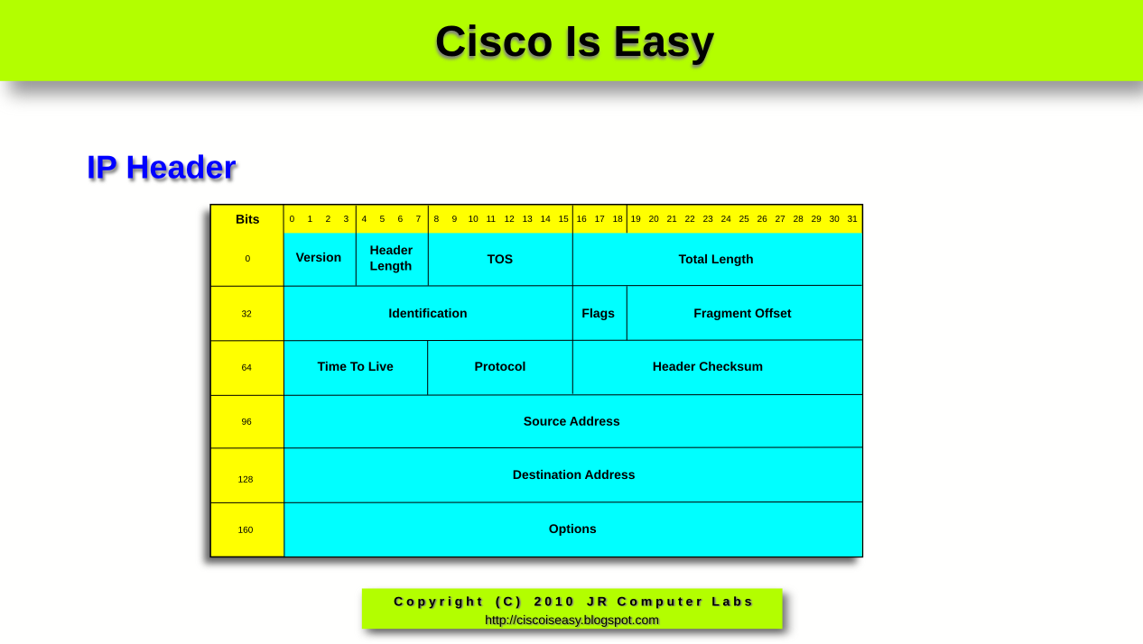
Internet Layer Header (layer 3)

Pic. 3 - IP Header


Data-Link Layer Header (layer 2)

Pic. 4 Ethernet Header (most commonly used technology in our LAN networks)

Click on the pictures to enlarge them.

NOTICE!
The following discussion has been simplified in order to help you understand the general process. Keep in mind that in reality, it is much more complex process than the explanation presented below.


Web Client to Web Server Transmission Step-by-Step

The best way to learn the theory is to see things working in practice. That is why, I am going to capture the web traffic initiated by my client computer destined to my web server. Before you delve into analyzing the details, please familiarize yourself with my client and server addresses first.

Web Client Details:
IP Address: 192.168.1.13 255.255.255.0
MAC Address: 00:24:e8:fa:07:1a

Web Server Details:
IP Address: 192.168.1.1 255.255.255.0
MAC Address: 00:50:bf:9c:45:6a

Step 1
In the URL field of my web browser I'm typing in the address of the server using HTTP protocol (Layer 5 protocol used as an example). This will tell the application what the address of the server is. I accept it by hitting the 'Enter' key.

Pic. 5 - URL Address of the web server


Step 2
The client computer realizes that the address of the recipient (web server) is in the same layer 3 network (the first 24 bits of the both source and destination address are the same). More on this, you will learn in the upcoming lessons. As a result of that, the client needs to obtain the MAC address of the web server first. Recall from the previous lesson that IP packet is encapsulated in layer 2 header, which in our case uses source and destination MAC addresses. Normally, the client computer is going to check the local 'arp cache' to find out if the mapping of the destination IP address to its MAC address is there. If not, like in my example, the client is going to issue 'ARP Request' message (Address Resolution Protocol) to learn the destination's computer MAC address. This request is propagated to ALL local machines in the network 192.168.1.0/24. Pay attention to the highlighted lines in the picture. The destination MAC address in the query is the Ethernet broadcast address: FF:FF:FF:FF:FF:FF. In the ARP request the client computer asks 192.168.1.1 for its MAC address (which, as of right now, is all 0s; see the below pic. 6).

Pic. 6 - ARP Request


NOTICE!
The ARP request is considered a layer 2 protocol. It is directly encapsulated in the Ethernet II frame. Its header is presented in the second line in the middle panel (under the 'Frame 3').


Step 3
There is only one computer with its unique address of 192.168.1.1 in the network. This one replies to the query with the 'ARP Reply' message back to the sender of the request, telling it what the MAC address it uses. The address is seen in the middle of the pic. 7 (highlighted) belongs to web server. The address reads:
00:50:bf:9c:45:6a

Pic. 7 - ARP Reply


Step 4
The MAC address of the web server was the missing piece of information the client needed to proceed with the TCP session establishment. TCP, being a session-oriented and reliable transport protocol, must establish the mutual communication with the web server first, before it is allowed to send the data from the web browser. This is known as the 3-way handshake. Let us look at the details of the first TCP segment in this session establishment phase.

1. The client (192.168.1.13) sends an 'empty' TCP segment (i.e. with no data from the application included in it).

  • It chooses a random source port number first. In the transmission presented the TCPSrc-Port: 51504 is chosen. Also it uses the Dst-Port: 80 which identifies web server destination application. This pair of ports will uniquely identify this particular transmission, as the client can initiate multiple transmissions at the same time. Those two ports (source and destination port numbers) allow multiple transmissions without a risk of 'mixing up' which reply from the servers should be sent back to which inititiating that request process. This way, the process that initiated transmission is going to receive the right reply. I need to add here that TCP and UDP ports are divided into two major groups: 'well-known ports' which are ports between 1-1023 (always destination ports for the client initiating transmissions), and 'ephemeral ports' between 1024-65535numbers. The latter ones, clients choose randomly to mark the source process for their transmissions.
  • Sequence Number in the segment = 0. If the web server (destination) receives this segment and replies to it, it will put a value of 1 in the Acknowledgment field. That is an indication for the client, that the first segment did arrive successfully at the server.
  • The SYN flag = 1, and all the rest of the flags are set to 0. It means,that this is the first handshake in the exchange. It is the client's request to establish session with the server.
  •  

    NOTICE!
    The layer 4 segment has been encapsulated in the layer 3 header (pic. 8: 'Internet Protocol') and further encapsulated in the Ethernet frame (pic. 8: Ethernet II). The first line in the middle section of the picture, is what is seen on the wire.


    Pic. 8 -  TCP Syn Segment


    2. The next segment captured (pic. 9) comes from the web server and is the reply for the 'SYN' message sent by the web client. Now, please compare both pictures (pic. 8 and pic. 9). Pay attention to the source and the destination TCP port numbers, and the source and destination addresses used in the layer 3 (IP header) and the layer 2 (Ethernet header). Did you notice they are reversed now?

    • TCP port numbers are now reversed (TCP Src-port=80, Dst-port=51504) in order to send the reply directly to the port that initiated the request).
    • The server's segment has the Sequence number=0, but the Acknowledgement number=1. It is what we expected. This means that the delivery of the client's first segment was successful).
    • The flag ACK=1, which is the acknowledgement for the SYN flag from the client.
    • The server also wants to synchronize the transmission with the client. That is why it sets its own SYN=1 in this segment.

    Pic. 9 - Server's response SYN, ACK


    3. The client needs to reply to the server's SYN message with its ACK=1 to finalize the session establishment (see the pic. 10). Here's what you find in the third handshake from the web client:

    • Src-port=51504, Dst-port=80.
    • Acknowledgement=1, which is to tell the server that its segment sequence=0 has arrived successfuly.
    • Sequence=1, which means that it is the second segment sent to the server. That's what the server expects to receive (in the next reply from the server, it should seeAcknowledgment=2).
    • The flag ACK=1, which is the response to the SYN=1 flag received from the server.
    This way, the 3-way handshake is complete!

    Pic. 10 - Final ACK from the server


    Step 5
    The client has established session with the server, so now it sends the first DATA packet (GET request), asking the server for its main page (look at pic. 11).

    Pic. 11 - Request from the client web browser 


    NOTICE!
    The data from the client (GET) is encapsulated in the layer 4 header, this in turn is encapsulated in the layer 3 header, and the whole thing further encapsulated in the layer 2 header. It is what I described in the lesson 5. See the details in the pic. 11.


    Step 6
    Finally, the reply comes back from the server to the client with the html page (see the pic. 12).

    Pic. 12 - Reply from the web server


    One last thing, I would like to bring up here. Since the appropriate layer understands its header (TCP-talks-to-TCP, IP-talks-to-IP, Ethernet-talks-to-Ethernet), we have two different inter-layer communications taking place:

    1. Vertical communication occurs when the upper layer is sending something to the lower layer and vice versa.
    2. Horizontal (virtual) communication between hosts when the destination host reads the appropriate header encapsulated by the sender. 
    Both are depicted in the picture below:

    Pic. 13 - Horizontal and vertical inter-layer communication.


    The content of this lesson is very simplified, just to get the juices flow. Below I present a short video which walks you through the whole process again. You might find it useful to fully understand the content of this lesson. If you caught the idea, please proceed to the next lesson.

    Lesson 4 - Introduction to TCP/IP Layers


    In this lesson we take a sneak peek at the fundamentals regarding TCP/IP. This is one of the most important aspects to understand in order to follow the upcoming lessons. It is not my ambition to explain everything here as this would turn into a hefty book to read. You can find a lot of them on the market anyway. Instead, I will try to focus on some basic aspects of TCP/IP. They will constitute the minimum knowledge to help us understand how computers communicate.

    If you feel the need to learn more on TCP/IP you can visit the following site: http://www.tcpipguide.com/free/t_toc.htm


    NOTICE!
    Familiarize yourself with ALL terms in red. They will be used throughout the classes.


    Introduction
    Computer communication follows some well defined rules and guidelines which we call protocols. In order for the computers to exchange data they have to agree on using the same rules, otherwise they become incompatible. That was the case in the past. This was one of the reasons to create a common model for communication. It was called OSI Model (Open Systems Interconnection). This was an attempt to make different vendor's computers exchange data easily. This way IBM machines could talk to DEC machines and so on. Today however, it is the TCP/IP model that is all-pervasive. This protocol suite is derived from OSI model and somewhat loosely follows its rules and terminology. This is going to be the focus of our discussion and the main topic of this lesson.

    Note!
    Remember that TCP/IP model does not follow OSI model exactly. OSI model is now used as a reference. What's described in this blog is TCP/IP model, not OSI or IPX/SPX model. Look at the comparison below:

    TCP/IP Layers
    The designers decided to break down the whole complexity of data exchange and created five layers of functions to accomplish the goal. This approach helps develop and modify certain layers of code without touching other layers. For instance, if you are an application programmer, you will be writing a code in the 'application layer' which allows you to use already written code dealing with the transport of data between computers. You do not even have to learn how this transport is done. It has already been written for you. This way, you focus on the application you're creating, what it does and how it works rather than learning about network adapter drivers, signaling and other gory, hardware details.

    TCP/IP model divides the functions related to data transmission by using five distinct layers of responsibility. Below area these layers.

    Layer 5-7 - Application
    This is where the data's journey begins. Everyday, you use many applications that  rely on network services. Those applications are classified to be layer 5 code. Your web browser and web server, mail client and mail server, ssh client and ssh server etc. You may have noticed the term client andserver often used in the above description. Pretty much all applications use this architecture.Client, is an application that requests some services from the server application. Server application is providing a client with what they want. A common example of that architecture is your Firefox orInternet Explorer web browser (client application) requesting a page from Apache or IIS web server (server application). Applications, in general, provide a User Interface (UI) which offloads us from a burden of knowing how a computer does things internally.

    So, once your application formed the request, that one is sent down to the layer 4 (transport layer) asking for the delivery to the host somewhere in the network.

    Layer 4 - Transport
    This layer accepts all requests coming from the upper layer (application layer) and tries to organize the transport of that request across the network. In TCP/IP model this layer of software is responsible for:

    • Breaking down big files that are sent across into smaller chunks called segments. There are technology limitations that do not allow our computers to send large files in one piece. It would not be a good idea anyway as any small change of the data during transmission would make the sender re-transmit the whole file again instead of the smaller chunk only. That of course, would take more time and resources to successfully transmit the data.
    • As your computer uses many applications that will transmit something across the network at the same time, the system must know how to mark those request such that they are delivered to the right receiver applications. And once the replies are coming back, they should be delivered back to the same process that initiated them. The concept of the port number has been introduced to deal with that. Source and destination ports ensure that all requests and replies are delivered to the appropriate processes on the computers exchanging data. More on that later in the upcoming lessons.
    • This layer also allows the application to use connection-oriented or connectionlessservices. The former, establishes communication with the receiving computer (or more generally: destination host) before data can be exchanged, the latter will send data without ensuring that the destination application is running and willing to receive anything. This form of transmission is used primarily for voice and video applications.
    • This layer will also give applications some options in terms of the reliability. Depending on which layer 4 protocol the application is designed to use, the reception of data can be verified or not. That creates reliable versus unreliable transport respectively. In the reliable transport any data that has not been delivered will be retransmitted, unlikely the unreliable transport.
    • One other function of layer 4 could be to moderate the transmissions so that the receiving host is neither swamped by the excess of packets coming in nor is it waiting and doing nothing because the sender's speed of transmission is too slow. Majority of the functions above are performed by TCP protocol, not UDP as applications choose one of them to use.
    Once all aspects and functions in this layer have been taken care of, layer 4 sends the data it received from layer 5 down to the layer 3 requesting its service.

    Layer 3 - Internet
    Upon receiving a request from layer 4, this code is going to process the incoming information. Since, typically we have more than one path between the sender (source) and the receiver (destination), the function of this layer is to find the best path between them. In order to accomplish that there are two concepts I need to introduce here.

    Firstly, we need to know how computers find themselves in the network. This is accomplished by using specially designed, layer 3 addresses uniquely identifying computers in any network. The addresses used by this layer consist of four bytes delimited by the dots (e.g. 10.1.1.1) which are followed by a, so called, 'netmask' also consisting of four bytes with the dot used as the delimiter (e.g. 255.255.255.0). The whole IP address can look like this:
    10.1.1.1 255.255.255.0. More on those later.

    Secondly, because the destination of our data can be outside of our own network, a device calledrouter has been introduced to find the optimal paths between the different networks in which the computers reside. The data processed by layer 3 is called a packet or datagram. This layer also uses a mapping to the upper layer 4 that has requested its services. This is due to the fact that there are more than one protocols available in layer 4 (TCP or UDP). This information (which layer 4 protocol is sending the data) is going to be useful when the data arrives at the destination and the destination's layer 3 process needs to send the content to the appropriate layer 4 protocol for processing. It has to be the SAME protocol that the sender used in layer 4.


    Layer 2 - Network Interface (Data Link in OSI model)
    There is a great variety of technologies that handle data transmission on media such as copper and fiber optics cables or air (wireless). In order to offload the layer 3 protocols from learning all possible signaling methods, layer 2 was created. Thus, layer 3 can focus on finding the best path between the source and the destination, and the layer 2 functions will handle the details of preparing the data to be placed on the actual media (copper wire, fiber, air etc.). The piece of information processed at this layer is called a frame. This layer will also use specially designed addressing scheme to recognize the next device which a computer is sending the data to. For instance, in the commonly used layer 2 technology called Ethernet, this address uniquely identifying hosts in the same network is called MAC Address. The reason why we use different addressing schemes: layer 3 and layer 2, will become clearer when we get into some details of the actual data exchange. Please, bear with me till we reach the right lesson that explains it in more detail. The device that is capable of understanding the structure of a frame and delivers the data between the hosts in the SAME network is called bridge, or switch. As of the time of writing this, switches are very popular devices and bridges can be found mostly in museums.

    Once the layer 2 has prepared the data which layer 3 requested to send, (the process is called 'framing'), layer 2 will send the request to layer 1 asking for the data to be placed onto the wire/fiber/air using the appropriate signaling method.

    Layer 1 - Network Interface (Physical Layer in OSI)
    This layer receives requests from layer 2 (data traveled from layer 5 to layer 1 now). The physical layer is going to encode data received from layer 2 software and place them in the form of bits (1s and 0s) on the medium. This way, ones and zeros travel across the media to deliver them to their receipient. The bits can traverse multiple devices as they go across such as hubs, switches, routers. What type of devices will forward those bits depends on the design of the network. The devices referred to as layer 1 devices are hubs, cables, network adapters, connectors,transceivers etc. Also the data processed by this layer is called bits. This layer defines low level aspects of the transmission such as cables used, maximum distance the cable can reliably sent bits across, types of the connectors, speed of the transmissions etc.


    NOTICE!
    The names given to the data at each of the layers described above (segment, packet, frame, bits) are taken from the OSI model terminology. They are referred to as: Protocol Data Unit (PDU).


    Understanding the terminology and the concepts presented in this lesson are the pre-requisites to understand the next lesson.

    Please, make sure that you read carefully this lesson before proceeding to lesson 5, where I am going to introduce you with some details regarding the protocols and headers used in TCP/IP transmissions.