Showing posts with label key. Show all posts

Mar 13, 2013

Lesson 46 - EIGRP Fundamentals Part 4 - Troubleshooting


In this post I'd like to show you how problems in EIGRP can manifest themselves and how to find and fix problems that are less conspicuous. All in the scope of the CCNA level.
Pic. 1 - Topology Diagram.
Icons designed by: Andrzej Szoblik - http://www.newo.pl

Let's assume that this is a new system and your colleague who's not experienced enough tried to set it up but with no success. Some work was done and the task at hand is to connect successfully the branches with headquarter accomplishing full reachability.

The first thing I'm going to do is to learn the topology diagram to know the addresses and encapsulations which connect the branches with the HQ network.

I log in to R1 and here's my first finding. Check it out:

Pic. 2 - EIGRP First Error.
The above output sent to the console indicates that R1 receives hello packets on its local S0/2 interface from the wrong address (not on common subnet). The IP address of the sender is: 172.32.14.4. R1's interface S0/2 is configured as 172.31.14.1. Clearly wrong address is assigned onR4.

I jump over to R2 and correct the address on S0/2 and make sure it is EIGRP enabled by typing in a right 'network' statement.

R4 Configuration:

!
R4(config)#int s0/2
R4(config-if)#ip address 172.31.14.4 255.255.255.0
R4(config-if)#router eigrp 1
R4(config-router)#no network 172.32.0.0
R4(config-router)#network 172.31.0.0
R4(config-router)#
!

I perform a simple check: I want to make sure that R4's interface S0/2 is running EIGRP protocol. Here's the output:

Pic. 3 - R4's EIGRP Interfaces.

To my great surprise, the interface is EIGRP-enabled but there R1 is not listed as the neighbor (peer). The ping shows no problems reaching R1 (172.31.14.1).

In this situation I decide to use a 'debug' tool. Be careful using 'debug' commands as they may severely impact the operation of the router. More information on how to use debug in lesson 37.

I disable a timestamps so the output of the debug is clearer. As soon as the first information is sent to the screen, I disable debug using 'u all' command (in case you are in other mode than privileged '#' the 'do u all' is used. It is the alias for: 'undebug all'. Here's what the debug reports.

Pic. 4 - Debug EIGRP Packets.

The output reveals that the local router (R4) has problems with authentication of EIGRP packets. Opcode =  5 (authentication off or key-chain missing).

The 'show key chain' shows ... zilch! There's no key chain defined on R4. I need to do it. I'm going to do to errors while configuring key chain in order to show you how they show in the 'debug ip eigrp' statement.

Here's my first erroneous configuration:

R4 Configuration: 

!
R4(config)#key chain EIGRP
R4(config-keychain)#key 2
R4(config-keychain-key)#key-string cisco
R4(config-keychain-key)#
R4(config-keychain-key)#int s0/2
R4(config-if)#ip authentication mode eigrp 1 md5
R4(config-if)#ip authentication key-chain eigrp 1 EIGRP
R4(config-if)#
!

You noticed that I used the key 2. Since, the neighbor adjacency has not been built, I reach for the 'debug eigrp packets' again. Here's the output now:

Pic. 5 - Another Debug EIGRP Packets.

In the ton of gibberish I fish out the above message: 'key not defined or not live'. This is the cause of  the 'invalid authentication'

I check R1 and see that it uses key 1 and not key 2. The mismatch in the key number prevents theR1 and R4 from establishing adjacency.

I'll make one more mistake so that you can see another error related to authentication. Look at my key chain authentication on R4:

Pic. 6 - Running Configuration - Key Chain.
At first glance, all seems okay. But is it?

Still R1 and R4 are not neighbors. Let's debug one more time.
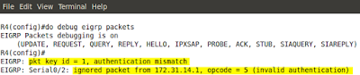
Pic. 7 - Debug EIGRP Packets.
This time there is no complaints about key number, but authentication still fails. The problem is with the password used. It does NOT match with the other end. Now, displaying configuration on both R1and R4 shows the password 'cisco'. But is it so? Check the below output on R4:
Pic. 8 - Show Key Chain.
A closer inspection shows that the password cisco is followed by a 'space' character which does not show in the 'show running-config'. This a cause of the problem.

One last error that shows without any debug. Check it out:

Pic. 9 - EIGRP Unsolicited Error Message.
The problem is with the K-values used by R5's neighbor (R2). They do not match on both ends. A quick look at R5 shows that default K-values are used.
Pic. 10 - Show IP Protocols on R5.

The same output on R2 reveals that it all K-values are used to calculate the metric. They do not match on both ends which results in lack of neighbor adjacencies between routers.
Pic. 11 - Show IP Protocols on R2.

A look at EIGRP configuration on R2:
Pic. 12 - EIGRP Configuration on R2.

 A quick fix on R2 and all is good!

R2 Configuration: 

!
R2(config)#router eigrp 1
R2(config-router)#no metric weights
R2(config-router)#
!


Incidentally, EIGRP unsolicited error messages are sent to the screen every few seconds which makes it hard to do the diagnostics. You can temporarily disable logging to the console 0 by typing:

R2(config)#no logging console 

To bring back the defaults:

R2(config)#logging console

In the next post, I'll look at the ACLs (Access Control Lists) and how they can serve different purposes in your network.

Lesson 44 - EIGRP Fundamentals Part 2 - Implementation


In the previous post (lesson 43) I have laid the foundations related to EIGRP terminology. Without understanding those keywords and their meaning it is hard to implement and analyze the behavior of this routing protocol.

The basic implementation steps, like in case of other routing protocols we have learned so far, requires two major steps:

  1. Enable EIGRP process in the 'config' mode.
  2. Instruct EIGRP which interfaces should participate in the EIGRP domain.
The second step is accomplished with the 'network' statement in the EIGRP routing context. This statement instructs EIGRP routing process which interfaces EIGRP will run on. The consequences of enabling EIGRP on the interface are similar to what we saw in OSPF configuration:
  • EIGRP-enabled interface begins to send EIGRP 'hello' packets in order to discover the neighbors. The address used to advertise these 'hello' packets is well-known, reserved multicast address: 224.0.0.10.
  • EIGRP-enabled interface allow the EIGRP process to read the address and network mask configured on this interface and advertise this network or subnet out other EIGRP-enabled interfaces where the neighbor(s) has/have been discovered and the relationship has been formed with them.
The 'network' statement can take a form of classful (as per IP class A, B, C; without a wildcard mask) or classless (using wildcard mask similar to OSPF) entry.

Also, worth noting here is that the command that starts the EIGRP process is followed by a number which is the Autonomous System number. Unlike OSPF which is the process ID and has local significance, AS number in EIGRP is important as it must match between the neighbors. Example of enabling EIGRP:

router eigrp 1

Number '1' is the Autonomus system number (between 1-65535) which must be the same on all EIGRP speaking routers in the domain.

The following list of parameters must match between EIGRP neighbors in order to successfully establish neighbor relationships: 

  1. Autonomous System number.
  2. K-Values (look at the previous lesson).
  3. If authentication is used both: the key number, the password, and the date/time the password is valid must match.
  4. The neighbors must be on common subnet (all IGPs follow this rule).
Since the 'network' keyword uses either a classful statement or it can take a wildcard mask (inversed mask) as its argument, consider the following four examples which accomplish the SAME goal: all interfaces of R3 are going to be EIGRP-enabled.
Pic. 1 - R3's 
Icons designed by: Andrzej Szoblik - http://www.newo.pl

Example 1

!
router eigrp 1
 network 172.31.0.0
!

Example 2 

!
router eigrp 1
 network 172.31.123.0 0.0.0.255
 network 172.31.3.0 0.0.0.15
 network 172.31.3.16 0.0.0.15
!

Example 3 

!
router eigrp 1
 network 172.31.123.0 0.0.0.255
 network 172.31.3.0 0.0.0.255
!

Example 4 

!
router eigrp 1
 network 172.31.123.3 0.0.0.0
 network 172.31.3.1 0.0.0.0
 network 172.31.3.17 0.0.0.0
!


They all achieve the same result: all interface become EIGRP-enabled.

EIGRP is partially a Distance Vector routing protocol. By default the automatic summarization to the class boundary takes place. The command that disables that behavior is: 'no auto-summary' used under EIGRP process.

EIGRP uses five different types of the packets to communicate. Three of them are reliable and must be acknowledged by the receiver. The EIGRP packets are as follows:

  1. Hello (unreliable).
  2. Updates (reliable).
  3. Queries (reliable).
  4. Replies (reliable).
  5. Acknowledgement (unreliable.

The last point I'd like to make relates to the ability of EIGRP to authenticate its packets. EIGRP currently (as of the time of writing this post) uses only one protocol which is MD5.

If you decide to configure authentication of EIGRP packets there are two major steps you must configure:

  1. Configure a key chain with the parameters such as the password(s) and the date/time they are valid.
  2. Apply authentication method and the key chain on per-interface basis.
Example of key chain configuration on R3 in Autonomous System 1. 
!
Key Chain Configuration
!
R3(config)#key chain EIGRP
R3(config-keychain)#key 1
R3(config-keychain-key)#key-string S3cr3t!!!
!
Enabling authentication on F1/0 interface - EIGRP AS 1 here
!
R3(config-if)#ip authentication mode eigrp 1 md5
R3(config-if)#ip authentication key-chain eigrp 1 EIGRP
R3(config-if)#
!

  • 'EIGRP' - The name of the key chain in my configuration. It can be any name.
  • 'key 1' - Number '1' must match be used on the neighbor's interface connected to R3's F1/0 interface.
  • 'S3cr3t!!!' - is the password used as the key 1. Must match between neighbors.
  • mode eigrp 1key-chain eigrp 1 - EIGRP AS number configured in the 'config' mode.
There are two other commands available under 'key 1' which I did not used:
  1. Accept-lifetime - date/time in which EIGRP packets signed with the digest based on the key-string will be accepted by the receiving router.
  2. Send-lifetime - date/time in which EIGRP packets will be signed using the key-string specified. The digest will be attached to all EIGRP packet types.
Since I did not use these two options (NTP time synchronization is needed), the key 1, using the password (here: S3cr3t!!!) is valid forever.


In the next post, I'm going to use this lesson's theory and put it into practice.

Mar 12, 2013

Lesson 37 - Routing Information Protocol Part3


In this post, I'm going to finish the RIP fundamentals by showing you RIPv2 in action. After reading this, you will see the major differences presented in the lesson 35 (table1) in practice. Also, I want to present the authentication of RIP packets which protects the RIP domain from being poisoned with false routes.

I'm going to use the same topology diagram as in previous lessons. Currently, the routers are running RIPv1. If you read my previous post, you saw the routing problems we ran into as RIPv1 does not advertise network masks along with IP addresses. The rules for sending and receiving updates are explained in lesson 36.

Pic. 1 - Topology Diagram.
Icons designed by: Andrzej Szoblik - http://www.newo.pl

As you remember, the subnets: 172.31.3.0/28 and 172.31.3.16/28 have not been advertised by RIPv1. There are a few solutions to this problem, but none of them can be resolved using RIPv1. The simplest solution is to use RIPv2 which is classless routing protocol.

Our current RIPv1 configuration looks like this (here: R1 given as and example).

Pic. 2 - R1's RIPv1 configuration

Now, let's enable RIPv2. Below is an example of R1's configuration. The two highlighted commands are now added on all routers in the topology.


R1 configuration:
R1#configure terminal
R1(config)#router rip
R1(config-router)#version 2
R1(config-router)#no auto-summary
R1(config-router)#network 172.31.0.0
R1(config-router)#passive-interface loopback1
R1(config-router)#end
R1#
  • version 2 - Enables RIPv2.
  • no auto-summary - Disables automatic summarization to a class boundary.
Technically, the 'no auto-summary' command is not necessary in this topology, but it will not do any harm. If a router has interfaces configured with IP subnets belonging to different IP classes, this command becomes mandatory if you want to advertise these subnets with their original network masks.

If you display the running configuration of R1, it is going to look like the one below :

Pic. 3 - R1's RIPv2 Configuration.
Now, let's look at the output of 'show ip protocols' on R3. You can compare it with RIPv1 output in the previous post (lesson 36).

Notice, the 'send and receive version'. Only RIPv2 updates will be sent and accepted now. Also, 'Automatic network summarization is not in effect' tells us that 'no auto-summary' command has been used. Also, both loopback interfaces are listed as 'Passive interface(s)'.

Pic. 4 - RIPv2 Information on R3.
It is also a good idea to see RIPv2 advertisements. Again, be careful using 'debug' commands. For better output, I have also disabled the time stamps:

R3 Configuration:

R3#configure terminal
R3(config)#no service timestamps
R3(config)#end


WARNING! 
Extreme care must be taken when using any debug commands on the production equipment. After the diagnostics have been completed, the debug command(s) must be turned off immediately.
All 'debug' commands are VERY dangerous if used on the production routers. They have enormous impact on the CPU and can potentially crash the device. They are typically used as the commands of the last resort during troubleshooting of a given technology when problem cannot be resolved without data they provide. So we tend to use them only in situations when we cannot do any more damage than there has already been done :-).


Pic. 5 - RIPv2 Debug Output on R3.
What are the major differences compared to RIPv1 output in the previous lesson?
  1. Sending and receiving update using version 2.
  2. Received networks/subnets via 0.0.0.0 mean that the advertising router (here: 172.31.123.2) is the best gateway to the given destination.
  3. Sending v2 update uses reserved multicast destination IP address 224.0.0.9 rather than broadcast.
Authentication of RIP Packets
Almost all routing protocols allow to authenticate their packets. This is an extra security mechanism used to protect your routing domain. It is easy to install a routing protocol on a computer and poison the routing domain with illegitimate prefixes. This can disrupt the operation of the whole routing domain.

RIP offers two ways of authenticating their packets:

  1. Simple Password (clear text) authentication.
  2. MD5 based (one-way algorithm) authentication.
Here, I am going to show the more secure one based on well know hashing algorithm called Message Digest 5.

There are three major steps to configure authentication in RIP:

  1. Configure a key chain - It allows to create multiple keys which can be changed automatically if the routers have the time synchronized. The name of the key chain does NOT have to be identical on all routers.
  2. Configure at least one key-string (password) in the key chain - Key number MUST be identical on all routers in the RIP domain. Also, the password (key-string) used for authentication must be identical on all routers.
  3. Apply the key chain - You must apply the key chain on the interfaces where RIP advertisements will be exchanged between the neighbors.

This configuration must be identical on all routers in the RIP domain. Here, I present the configuration on R3.

Step 1
Create a key chain. The name of the key chain (here: RIP).

R3#configure terminal
R3(config)#key chain RIP
R3(config-keychain)#

Step 2
Configure at least one key-string (password) in the key chain (must be identical on all routers). I do not use additional options allowing the key-string to timeout. The password used is valid forever.

R3(config-keychain)#key 1
R3(config-keychain-key)#key-string secret123
R3(config-keychain-key)#exit
R3(config-keychain)#exit
R3(config)#

Step 3
Apply the key chain on the appropriate interface(s). Here the packets must be authenticated between R1 and R2 routers so interface F1/0 will use the key chain.

R3(config)#interface f1/0
R3(config-if)#ip rip authentication mode md5
R3(config-if)#ip rip authentication key-chain RIP
R3(config-if)#end
R3#

If you display information about RIP again, you will notice that authentication of RIP packets has been enabled.

Pic. 6 - RIPv2 Authentication.
If neighbors (R1 and R2) do not sign their packets using the same key number and key-string, R3 is going to reject their advertisements. Both R1 and R2 send their update without authentication. The result is that R3 must ignore them.

Check it out:

Pic. 7 - Invalid Authentication.

Once I have configured identical authentication on all routers, here is the debug output showing thatR1 is sending RIP packets with proper authentication.
Pic. 8 - Authenticated RIPv2 Update from R1.

In the next post, I will start exploration of, arguably, the most commonly used routing protocol OSPF.