Mar 13, 2013

The blog's Content list


Disclaimer
The author of the posts will not assume any liability or responsibility to any person or entity with respect to loss or damages incurred from information contained in this blog.


 Quickly navigate to lesson ...
L01 L02 L03 L04 L05 L06 L07 L08 L09 L10
L11 L12 L13 L14 L15 L16 L17 L18 L19 L20
L21 L22 L23 L24 L25 L26 L27 L28 L29 L30
L31 L32 L33 L34 L35 L36 L37 L38 L39 L40
L41 L42 L43 L44 L45 L46 L47 L48 L49 L50
L51 L52 L53 L54 L55 L56 L57 L58

                                  The Blog's Content list

4 - Introduction to TCP/IP Layers
5 - Encapsulation and De-encapsulation Process
6 - Example of TCP/IP Traffic Flow
7 - Building a Home Network
8 - Ethernet and Hub Operations
9 - Bridging/Switching Learning Process
10 - Cisco Discovery Protocol
11 - Layer 2 Connectivity Troubleshooting Part 1
12 - Layer 2 Connectivity Troubleshooting Part 2
13 - Layer 2 Connectivity Troubleshooting Part 3
14 - NTP and Syslog Services
15 - VLANs Overview
16 - VLANs In Practice
17 - Inter VLAN Traffic Flow Analysis
18 - VTP and VLAN Quiz
19 - Spanning-Tree Protocol Overview
20 - Spanning-Tree Protocol Operation
21 - Spanning-Tree Protocol in Practice
22 - Spanning-Tree Cisco Enhancements
23 - Introduction to Rapid STP (802.1w)
24 - Layer 2 Etherchannel
25 - Switch Port Security
26 - Binary World
27 - IPv4 Address Dissected - Part 1
28 - IPv4 Address Dissected - Part 2
29 - IPv4 Subnetting - The Rules
30 - IPv4 Subnetting - Practice
31 - What is a Router ?
32 - Route Selection Process Demystified
33 - Static Routing
34 - Dynamic Routing Protocols Introduction
35 - Routing Information Protocol Part 1
36 - Routing Information Protocol Part 2
37 - Routing Information Protocol Part 3
38 - OSPF Fundamentals Part 1 - Terminology
39 - OSPF Fundamentals Part 2 - Hello Packets
40 - OSPF Fundamentals Part 3 - RouterID and DR/BDR
41 - OSPF Fundamentals Part 4 - Implementation
42 - OSPF Fundamentals Part 5 - The Lab
43 - EIGRP Fundamentals Part 1 - Overview
44 - EIGRP Fundamentals Part 2 - Implementation
45 - EIGRP Fundamentals Part 3 - The Lab
46 - EIGRP Fundamentals Part 4 - Troubleshooting
47 - Packet Filtering with Standard ACL
48 - Standard ACL Examples
49 - Packet Filtering with Extended ACLs
50 - Extended ACL Examples
51 - Network Address Translation Part 1
52 - Network Address Translation Part 2
53 - Network Address Translation Part 3
54 - Network Address Translation Part 4
55 - Introduction to IPv6 - Addresses
56 - Introduction to IPv6 - Address Structure
57 - Introduction to IPv6 - Address Configuration
58 - Introduction to IPv6 - Migration


Lesson 58 - Introduction to IPv6 - Migration


Now, being equipped with some fundamental IPv6 knowledge, we can try to configure RIPng protocol (RIP Next Generation), as well as try to connect two different IPv6 networks over IPv4 cloud. I'm going to use the same topology in the previous lesson.
Pic. 1 - IPv6-IPv4 Topology Diagram.
Icons designed by: Andrzej Szoblik - http://www.newo.pl

Let's start off with enabling RIPng between R1 and R3 followed by some verification steps. RIPng is very similar to RIPv2 we used before. It uses similar mechanism such as split-horizon, maximum hop-count (16 hops), advertisements every 30 seconds, etc. It uses UDP port 521 (RIP uses UDP port 520).

  
Step 1
Configure IPv6 and IPv4 addresses and enable the interfaces. Check point-to-point reachability.

R1 Configuration:

!
interface Loopback0
 no ip address
 ipv6 address 2001:1:1:1::1/64
!
interface FastEthernet1/0
 no ip address
 duplex auto
 speed auto
 ipv6 address 2001:13:13:13::1/64
!
interface Serial0/0
 ip address 10.1.1.1 255.255.255.252
!

R2 Configuration:

!
interface Loopback0
 no ip address
 ipv6 address 2001:2:2:2::2/64
!
interface FastEthernet1/0
 no ip address
 duplex auto
 speed auto
 ipv6 address 2001:24:24:24::2/64
!
interface Serial0/0
 ip address 10.1.1.2 255.255.255.252
!

R3 Configuration:

!
interface Loopback0
 no ip address
 ipv6 address 2001:3:3:3::3/64
!
interface FastEthernet1/0
 no ip address
 duplex auto
 speed auto
 ipv6 address 2001:13:13:13::3/64
!

R4 Configuration:

!
interface Loopback0
 no ip address
 ipv6 address 2001:4:4:4::4/64
!
interface FastEthernet1/0
 no ip address
 duplex auto
 speed auto
 ipv6 address 2001:24:24:24::4/64
!

Verification:

Pic. 2 - IPv6 Ping Test on R1.

Pic. 2 - IPv6 Ping Test on R2.

Since, pinging by IPv6 address is a bit awkward, you can create name-to-ip mapping using the following commands (here: R1 as an example):

R1 Configuration:

!
R1(config)#ipv6 host R3 2001:13:13:13::3
R1(config)#end
!

Then, you can 'ping R3' (name is case insensitive) instead of using its address.

The routing table of R1 looks like this. You should recognize the addresses easily based on the previous post.

Pic. 4 - R1's IPv6 Routing Table.

Step 2
Enable RIPng to advertise loopbacks. Check the reachability.

In order to support IPv6 routing, you must enable support for it using:
'ipv6 unicast-routing'. Starting RIP process will require to configure a tag for the process (can be number or name). Then, you enable RIPng on the interfaces in question (note: there is no network statement to do that).

R1 Configuration:

!
ipv6 unicast-routing
!
ipv6 router rip TEST
!
interface Loopback0
 no ip address
 ipv6 address 2001:1:1:1::1/64
 ipv6 rip TEST enable
!

interface FastEthernet1/0
 no ip address
 duplex auto
 speed auto
 ipv6 address 2001:13:13:13::1/64
 ipv6 rip TEST enable
!

R2 Configuration:

!
ipv6 unicast-routing
!
ipv6 router rip TEST
!
interface Loopback0
 no ip address
 ipv6 address 2001:2:2:2::2/64
 ipv6 rip TEST enable
!
interface FastEthernet1/0
 no ip address
 duplex auto
 speed auto
 ipv6 address 2001:24:24:24::2/64
 ipv6 rip TEST enable
!

R3 Configuration:

!
ipv6 unicast-routing
!
ipv6 router rip TEST
!
interface Loopback0
 no ip address
 ipv6 address 2001:3:3:3::3/64
 ipv6 rip TEST enable
!
interface FastEthernet1/0
 no ip address
 duplex auto
 speed auto
 ipv6 address 2001:13:13:13::3/64
 ipv6 rip TEST enable
!

R4 Configuration:

!
ipv6 unicast-routing
!
ipv6 router rip TEST
!
interface Loopback0
 no ip address
 ipv6 address 2001:4:4:4::4/64
 ipv6 rip TEST enable
!
interface FastEthernet1/0
 no ip address
 duplex auto
 speed auto
 ipv6 address 2001:24:24:24::4/64
 ipv6 rip TEST enable
!

Verification (here just on R1):

Pic. 5 - R1's RIPng Routing Table.

Note!
R3's Loopback has been advertised to R1. The next-hop-address is the R3's link-local address, NOT the globally unique IPv6 address.

Pic. 6 - Debugging RIPng.

Take time and effort in analyzing the output of the debug. Pay attention to the UDP port number used. It is 521 (RIPv1 and RIPv2 use 520). Also notice that the source IPv6 is the router's link-local address and not globally unique one. Also, the destination address is IPv6 multicast address reserved for RIPng: FF02::9.
Another, worth noting fact is that R3 advertises its loopback (2001:3:3:3::/64) and its locally connected network (2001:13:13:13::/64). 

One more command to check RIPng configuration.

Pic. 7 - IPv6 Protocols.

Step 3
Create tunnel between two IPv6 networks over IPv4 island.

Since CCNA official course does not teach how to create tunnels, I will use 6to4 tunneling method which encapsulates IPv6 packet in IPv4 headers to send them across IPv4 network. These posts do not aspire to help you pass the exam. They are designed as an extra, practical help to master the technologies at the CCNA level instead.

R1 Configuration:

!
interface Tunnel0
 no ip address
 ipv6 address 2001:12:12:12::1/64
 ipv6 rip TEST enable
 tunnel source 10.1.1.1
 tunnel destination 10.1.1.2
 tunnel mode ipv6ip
!

R2 Configuration:

!
interface Tunnel0
 no ip address
 ipv6 address 2001:12:12:12::2/64
 ipv6 rip TEST enable
 tunnel source 10.1.1.2
 tunnel destination 10.1.1.1
 tunnel mode ipv6ip
!

Verification:

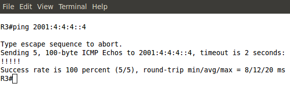
Pic. 8 - R3's IPv6 Routing Table.

Pic. 9 - Ping Test from R3 to R4.

The Cisco documentation on how to implement IPv6 is available at:
http://www.cisco.com/en/US/docs/ios/ipv6/configuration/guide/12_4/ipv6_12_4_book.html 

If you want to learn more on tunneling methods used during the migration look at:
http://www.cisco.com/en/US/docs/ios/ipv6/configuration/guide/ip6-tunnel.html

Another method called NAT-PT (NAT Protocol Translation) can is explained at:
http://www.cisco.com/en/US/docs/ios/ipv6/configuration/guide/ip6-nat_trnsln_ps6350_TSD_Products_Configuration_Guide_Chapter.html

In my next post, I will address the basics of WAN technologies including some legacy technologies such as Frame-Relay since they are still part of the exam game.

Lesson 57 - Introduction to IPv6 - Address Configuration


It's time to put our hands to work now. Let's see how we can configure IPv6 addresses. I'm going to use the following topology diagram to present different options with regard to IPv6 address configuration on router's interfaces.
Pic. 1 - IPv6-IPv4 Topology Diagram.
Icons designed by: Andrzej Szoblik - http://www.newo.pl

I will use R1 and R3 to begin with. The whole 'Introduction to IPv6' series will end with connecting these two IPv6 networks over IPv4 cloud to show you one of many migration options available.

As you already know, each IPv6-enabled interface, be it a router or computer's interface, will use two distinct addresses:
  • link-local (FE80::)
  • global (2000::)
Currently there are two global prefixes in use (as of writing this post):
  • 2001 - global addresses
  • 2002 - 6to4 tunnel (without actually creating a tunnel interface).
Let's open R1's console and configure IPv6 address on F1/0 interface. First, I'll use EUI-64 method to derive the host bits based on the MAC address. Take a look:
Pic. 2 - IPv6 Address with EUI-64.

Note, that by just configuring IPv6 on the interface, IPv6 protocol stack gets turned on automatically. You can verify this like shown below:

Pic. 3. IPv6 Address Verification

There area two methods of turning on IPv6 support on an interface in IOS:
  • By using 'ipv6 enable' command.
  • By configuring global IPv6 address.

Both link-local and global addresses are now configured. The subnet is what I typed in, the host portion created based on the MAC address taken from F1/0 interface. Do we always have to use EUI-64? Of course not. Both link-local and global addresses can be created automatically. I have removed the previous configuration (pic. 3) and configured this instead:

Pic. 4 - IPv6 Manual Address Assignment
(link-local and global).

Both addresses (link-local and global) are configured manually. Verify this below now:

Pic. 5 - Verification.

Okay. Let's bring the R1's interface F1/0 up, and jump over to R3 for a moment to configure its F1/0 interface ... differently!

An alternative to the above methods (it is going to be used primarily on the computers rather than routers) is so called 'autoconfig' method. For this method to work you must configure two commands first (as of writing this post in most IOS versions I came across both of these must be turned on):

R1 Configuration: 

R1(config)#ipv6 unicast-routing

R3 Configuration: 

R3(config)#ipv6 unicast-routing
R3(config)#int f1/0
R3(config-if)#ipv6 enable
R3(config-if)#ipv6 address autoconfig

Let's verify configuration of IPv6 with this method!

Pic. 6 - Verification.

The moment I enabled 'ipv6 unicast-routing', the router begins to support this method. R3configured as 'autoconfig' will obtain the network portion of the global address (the most significant 64 bits) from the local router (here: R1) by sending a special message called: Router Solicitation(RS). R1, upon receiving this message is going to reply with Router Advertisement (RA). This way,R3 learns what the network portion of the global address is and using EUI-64 completes the host portion, thus creating full, globally unique address to operate.

In IPv6 world there are no broadcasts, so the neighbor discovery using ARP is no longer working. The neighbor discovery, layer 3 to layer 2 address mapping are done using ICMPv6 protocol. There are four ICMPv6 Neighbor Discovery messages you must be aware of. These are:
  • NS - Neighbor Solicitation, asking for neighbor information.
  • NA - Neighbor Advertisements, introducing yourself to the neighbors.
  • RS - Router Solicitation, asking for info about local routers.
  • RA - Router Advertisements, advertising yourself as an active router.
Let's enable few debugs (remember that these are dangerous commands on production equipment) and see few of these messages being exchanged.

Pic. 7 - Debugging ICMPv6 Communication.

ICMPv6-ND: DAD: FE80::CE02:6FF:FE1E:10 is unique.
The above messages is the Duplicate Address Detection (DAD; mechanism of checking if the link-local is unique).
ICMPv6-ND: Sending NA for FE80::CE02:6FF:FE1E:10 on FastEthernet1/0
IPV6: source FE80::CE02:6FF:FE1E:10 (local)
      dest FF02::1 (FastEthernet1/0)
After checking that R3's link-local address is unique, it introduces itself to all the neighbors on F1/0 interface (Neighbor Advertisement).
ICMPv6-ND: Sending RS on FastEthernet1/0
IPV6: source FE80::CE02:6FF:FE1E:10 (local)
      dest FF02::2 (FastEthernet1/0)
R3 is sending Route Solicitation trying to discover locally active routers in order to obtain the information about the network portion of the global address.
ICMPv6: Received ICMPv6 packet from FE80::1, type 134
ICMPv6-ND: Received RA from FE80::1 on FastEthernet1/0
R3 receives information from R1 (R1's Router Advertisement)
ICMPv6-ND: Sending NS for 2001:13:13:13:CE02:6FF:FE1E:10 on FastEthernet1/0
IPV6: source :: (local)
      dest FF02::1:FF1E:10 (FastEthernet1/0)
R3 is sending the Neighbor Solicitation trying to discover the neighbors. I already knows the 2001:13:13:13::
ICMPv6-ND: Autoconfiguring 2001:13:13:13:CE02:6FF:FE1E:10 on FastEthernet1/0
R3's autoconfiguration is complete.
ICMPv6-ND: DAD: 2001:13:13:13:CE02:6FF:FE1E:10 is unique.
R3's 128-bit global address is unique (Duplicate Address Detection).
ICMPv6-ND: Sending NA for 2001:13:13:13:CE02:6FF:FE1E:10 on FastEthernet1/0
IPV6: source 2001:13:13:13:CE02:6FF:FE1E:10 (local)
      dest FF02::1 (FastEthernet1/0)
      traffic class 224, flow 0x0, len 72+8, prot 58, hops 255, originating
IPv6: Sending on FastEthernet1/0
ICMPv6-ND: Address 2001:13:13:13:CE02:6FF:FE1E:10/64 is up on FastEthernet1/0
R3 is announcing its presence on F1/0 segment (Neighbor Advertisement) and fully configured to operate using IPv6 address.

Note, that the ND (ICMPv6 Neighbor Discovery) communication uses multicast (FF). Two addresses are used here:

FF02::1 - All local hosts on the link.
FF02::2 - All local routers on the link.

One last thought about EUI-64 and link-local address. Since, it is locally significant, this address will be used on ALL interfaces. The reason I mention this is that if you try to check connectivity between link-local interfaces, you must provide the router with the output interface. It uses this address on ALL of them after all. Also, you must type in the full interface name to send icmp echo message using link-local address. Check it out:

Pic. 9 - Ping Connectivity Test.

Let's check R3's neighbors (layer 3 to layer 2 mapping):
Pic. 10 - IPv6 Layer 3 to Layer 2 Mapping.

Yes, this would be your IPv6 equivalent of the 'show arp' command used in IPv4!

In my next post we will configure RIPng (RIP Next Generation) routing protocol. The 'Introduction to IPv6' will finish with a short discussion on IPv4 to IPv6 migration and a quick lab to see how we can route IPv6 packets over IPv4 networks.

Lesson 56 - Introduction to IPv6 - Address Structure


After a very short introduction to IPv6 types of addresses and the header presentation, let's dig deeper and find out more about IPv6 addresses.

Hexadecimal Address Notation
I have already mentioned that IPv6 global space begins with 2000::/3. This means that all public IPv6 addresses now use three bits which amount to value 2 in hex.

Look at this notation of global address one more time:

2000::/3
This is a shortcut for:

2001:0000:0000:0000:0000:0000:0000:0000/3

And just like in IPv4 addresses this '/3' tells us to pay attention to the three most significant bits. Hexadecimal to binary conversion is simple. Two digits in hex (for instance: 20) is a one byte value (eight bits). One character stands for four bits (called a nibble). They need to be converted as two separate entities.

Pic. 1 - Hex-to-Binary Conversion.


This way, the hexadecimal 20 becomes 00100000.

In the global IPv6 address scope the first three bits ('/3') will always be set like shown below (as of writing this post):

Pic. 2 - IPv6 Global Address Sequence of Bits.

Okay. What about the hierarchy in IPv6 address?

IPv6 Hierarchy
It is not very different from what we used in IPv4 classes! Do you remember these bits settings in IPv4? If not, look at the below numbers:

Class A - 0xxxxxxx.xxxxxxxx.xxxxxxxx.xxxxxxxx /8
Class B - 10xxxxxx.xxxxxxxx.xxxxxxxx.xxxxxxxx /16
Class C - 110xxxxx.xxxxxxxx.xxxxxxxx.xxxxxxxx /24

The blue color denotes the network portion of the address in these classes. For instance, the '/24' means that 24 most significant bits are the network bits. The remaining ones (eight of them left) are the host bits. This way we create the hierarchy in IPv4 addresses. 


What does it look like in IPv6 then? It is much simpler. See for yourself:

2001:acbd:1234:a1b2:0000:0000:0000:0001/64

The first sixty four bits (blue) are network bits, the remaining ones are the host's interface identifier (host bits). But this, we already know based on the previous post. The network portion is going to be given to us either by the ISP or by the registry (ARIN in the US, RIPE in Europe etc.) if we're a big organization. 

We're told that the length of the prefix assigned to different organizations looks like this:
  • Registries will be assigned /23
  • ISP will be assigned /32
  • Sites will be assigned /48
Say, you are the organization that receives /48 prefix like this:
2001:1234:5678:0000:0000:0000:0000:0000/48.

This gives you two bytes (shown in red) in the network portion to create different networks (red portion: 2^16=65536 different numbers). By the way, get used to the shortcuts:

2001:1234:5678:0000:0000:0000:0000:0000/48 = 2001:1234:5678:0000::/48
IPv6 Interface Identifier (host bits)
How do we get the host portion then? 

In terms of creating the host portion of IPv6 address, if DHCP is not used, we have two options. One way is to do this by hand like presented below (the red color is the interface identifier or the host bits if you will):

2001:1234:5678:1000::1
(abbreviated address which could be expanded to 2001:1234:5678:1000:0000:0000:0000:0001)

But this approach seems somewhat tedious. I mean, who wants to assign addresses on 500 hosts this way?

Another way is to use EUI-64 method which creates the host portion of IPv6 address based on the MAC address of the first Ethernet interface which, at least in theory, should be unique!

Because the MAC address has only 48 bits and not 64, a special procedure has been developed to fill in the gap. Check it out the MAC address of the interface on the router:

Pic. 3 - MAC address of F1/0 Interface.

In the EUI-64 method the operating system takes the MAC address (highlighted) and uses it to create the host bits for the link-local address by default (you can also do this manually). And the same method can be used to assign the host bits in the global address.

Here is the detailed description of how 48 bits of MAC address becomes 64 bit host portion of IPv6 address in EUI-64 method (operating system takes care of these details itself).

Step 1
Flip the 7th bit (counting from left to right) in the MAC address (if it's 1 change it to 0, if it's 0, change it to 1).

In order to do that, operating system must first convert the hexadecimal number of the first byte to the binary form. MAC address used in the example is (as per pic. 3):

CC00.19BA.0010.

(Hex) CC ==> (Bin) 11001100
C=1100

Counting from left to right the 7th bit is: 11001100. This one must be flipped like shown below:
11001110. This gives us the hexadecimal value of: CE.

Step 2
Use the MAC address after modifying the 7th bit in step 1 and inject the FFFE between OUI (first three bytes on the left) and the serial number of the adapter (first three bytes on the right). I will use the colon (:) as the delimiter and blocks of 2-bytes to make it compliant with the IPv6 convention. Look at the result below:

CE00:19FF:FEBA:0010

This way we get 64-bit host portion of the IPv6 address. So my link-local address which uses this method to create the host bits will look like this:

CE00:19FF:FEBA:0010, which is abbreviated to this form:
CE00:19FF:FEBA:10

Step 3
Add the network portion to this construct calculated in step 2. For instance, we know that link-local's network bits are always FF80::/10. So, the whole link-local address is going to be (abbreviated as per Lesson 55's explanation):

FF80::CE00:19FF:FEBA:10
(again, the full 128-bit version is: FF80:0000:0000:0000:E00:19FF:FEBA:0010)

Let's see if this is true when I enable IPv6 support on F1/0 interface. Pay attention to link local address value.

Pic. 4 - IPv6-enabled F1/0 Interface.

Note that just by enabling IPv6 support on the interface IOS automatically creates link-local address using EUI-64, allowing this interface to communicate with hosts residing on this local subnet/network. However, in order to communicate with hosts outside this link-local network, the interface needs a global address as well. This leads us to a correct conclusion that each interface will have two addresses: link-local and global in order to fully operate in IPv6 domain.
IPv6 Global Address Configuration
There are two major methods of configuring IPv6 addresses on our devices:
  • Manual method - You will configure them like we sometimes do with IPv4 right now.
  • Dynamic method - This one offers us IPv6 DHCP servers or the hosts can obtain the network portion of the IPv6 address from their local router (special message is sent called 'Router Solicitation'). In the latter situation the host portion will be generated automatically using the EUI-64 method described above.
Since this post has enough information for one sitting, I'll show you the manual and router solicited methods of configuring IPv6 addresses in my next post. I will also explain what happened to our IPv4 ARP request since broadcast does not exist in IPv6 world anymore!

Lesson 55 - Introduction to IPv6 - Addresses


Network Address Translation I have rambled about in the last four posts, is designed to deal with a rapid IPv4 address depletion. The scope of 32 bits, allows to allocate 4 294 967 296 unique numbers. Even though, it seemed a lot in late 80s, the exponential growth of the Internet in 90s showed us that 4.3 billion addresses are not enough to uniquely identify our devices these days. The solution to the problem, at least for now, is to use IP version 6.

But what happened to IPv5?
I have found the answer to this question at:
http://compnetworking.about.com/b/2008/11/05/what-happened-to-ipv5.htm

IPv6 Header
IPv6 Header has been simplified in order to improve the efficiency on the routers. Fewer header fields to process, allow faster transmissions. Take a look at the comparison between IPv4 and IPv6 headers:

Pic. 1 - IPv4 Header.

Pic. 2 - IPv6 Header.
Pic. 3 - IPv4 and IPv6 Header Field Comparison.
Source:
http://www.cisco.com/en/US/tech/tk872/tech_white_papers_list.html

(IPv6 Headers at Glance.pdf)

IPv6 header does not use checksum, the TTL field has been replaced with Hop Limit name, and packets will no longer be fragmented (Path MTU Discover is going to be performed or the minimum MTU must be used: 1280 bytes).

IPv6 uses 128-bit addresses and offers us quite a number of unique identifiers:

3.4 x 10 ^ 38

So the number of addresses available is this:

340,282,366,920,938,463,463,374,607,431,768,211,456

Chances are that we will not run out of these till the end of this century.

In IPv6 designers gave up on broadcast transmissions. They have been replaced with multicast and unicast.

IPv6 Address Notation
Decimal notation has been replaced with hexadecimal using 16 characters (0,1,2,3,4,5,6,7,8,9,a,b,c,d,e,f). A=10, B=11, C=12 etc. You can use both upper and lower cases to address your device since the numbers are case insensitive.

IPv6 address consists of eight groups of four characters (2-byte values) delimited with the colon (:). Take a look at this address:

2001:0db8:65a3:0000:0000:5d2e:0370:7134

Addresses still use the hierarchy like we in IPv4. They are divided into two parts. The green one (64 bits) denotes the network portion, and the blue one is a interface identifier. Since it would be tedious to type in all these numbers, we can use few shortcuts. 

  • Leading zeros can be omitted
  • Groups of four zeros can be abbreviated to a zero
  • Multiple contiguous groups (2-byte groups) can be abbreviated to double colon (::) but only once.
Look at these examples below.

Leading zeros omitted: 
2001:0db8:65a3:0000:0000:5d2e:0370:7134 can be abbreviated to:
2001:db8:65a3:0000:0000:5d2e:370:7134

Groups of four zeros can be abbreviated to a zero:
2001:0db8:65a3:0000:0000:5d2e:0370:7134 can be abbreviated to:
2001:0db8:65a3:0:0:5d2e:0370:7134 can be abbreviated to:

Multiple contiguous groups (2-byte groups) can be abbreviated to double colon (::) but only once
2001:0db8:65a3:0000:0000:5d2e:0370:7134 can be abbreviated to:
2001:0db8:65a3::5d2e:0370:7134

Following all these shortcuts:
2001:0db8:65a3:0000:0000:5d2e:0370:7134 will be represented

2001:db8:65a3::5d2e:370:7134

Types of IPv6 addresses
There are few types of addresses w need to know about. These are:

  1. Global Addresses - Unique, global addresses used on the Internet. They use the following prefix 2000::/3.
  2. Link Local Addresses - Used to communicate with hosts on the same physical or logical network. These addresses start with FE80::/10
  3. Site Local Address - The equivalent of RFC1918 (private addresses) but they are being deprecated. They start with FEC0::/10 prefix.
  4. Multicast Address - Multicast replaces broadcast (along with unicast). The addresses use the following prefix: FF00::/8.
In my next post, I will show you simple configuration of these addresses on the command line interface.